
Heat-coupled phenol-ammonia wastewater treatment device and method

A heat coupling and wastewater treatment technology, applied in multi-stage water treatment, water/sewage treatment, water treatment parameter control, etc., can solve the problem of not necessarily meeting the heat demand of individual phenol towers, lack of backup external heating for phenol towers and water towers, The problem of high ammonia content in the steam at the top of the deammonization tower can achieve the effect of improving heat availability, low ammonia content, and reducing equipment materials

Pending Publication Date: 2020-10-13
TIANJIN AOZHAN XINGDA TECH
View PDF1 Cites 4 Cited by
  • Summary
  • Abstract
  • Description
  • Claims
  • Application Information

AI Technical Summary

Problems solved by technology

Although this process route can achieve the purpose of energy saving, the ammonia content of the steam at the top of the deammonization tower is high, the temperature is relatively low, and the requirements for the negative pressure of the phenol tower and water tower that receive heat are relatively high; the steam at the top of the deammonization tower can provide The heat depends on the feed and reflux ratio of the deamination tower, and it may not fully meet the heat demand of the phenol tower and water tower, or even the heat demand of a single phenol tower, which lacks backup external heating

Method used


Image

  • Heat-coupled phenol-ammonia wastewater treatment device and method
  • Heat-coupled phenol-ammonia wastewater treatment device and method

Examples


Embodiment 1

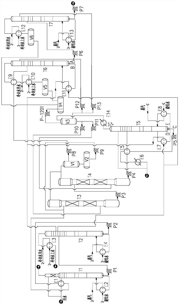
[0047] Example 1: Such as figure 1 As shown, the steam produced by the ammonia removal tower T2 first exchanges heat with the reboiler of the previous solvent recovery tower T6, and the condensed water after the heat exchange is mixed with the steam and then passes through a reboiler E7 of the water tower T5. After the second heat exchange, the condensate after the second heat exchange returns to the side line extraction position or the next layer of the extraction position in the ammonia removal tower T2.

Embodiment 2

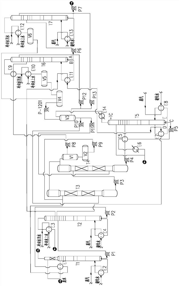
[0048] Example 2: Such as figure 2 As shown, the steam produced by the ammonia removal tower T2 is divided into two streams, one for heat exchange with the reboiler of the previous solvent recovery tower T6, the other for heat exchange with a reboiler E7 of the water tower T5, and the two respectively The condensate after heat exchange through the reboiler E7 is merged back to the side line extraction position or below the extraction position in the ammonia removal tower T2.

[0049] The crude ammonia gas is discharged from the top of the T2 tower of the ammonia removal tower, the temperature is 135~145℃, the crude ammonia gas is condensed by cooling water through the condenser E3 of the ammonia removal tower, and the temperature is controlled at 50~80℃;

[0050] The deamination tower in the present invention is operated under pressure, the operating pressure at the top of the deamination tower is 350-500kPa(g), and the operating temperature is 135-163°C; the deammination tower re...


PUM


Abstract

The invention discloses a heat-coupled phenol-ammonia wastewater treatment device. The device comprises a raw material preheater, a deacidification tower, a deamination tower, a water tower and two stages of extraction towers connected with an extract tank in series along a direction from front to back, wherein the two stages of extraction towers are connected with two stages of solvent recovery towers which are connected in series along a direction from front to back; sulfur-containing components are removed from the wastewater through the deacidification tower; ammonia nitrogen in the wastewater is removed through the deamination tower; as the wastewater is extracted through the two stages of extraction towers in sequence, phenol in the wastewater is extracted to an extraction phase andextracted from the top of the extraction tower to serve as a feed of a solvent recovery tower; crude phenol is extracted from the bottom of the latter-stage solvent recovery tower after the wastewateris treated by the two stages of the solvent recovery towers in sequence, and a solvent is extracted from the top of the solvent recovery tower; and meanwhile, a raffinate phase extracted from the bottom of the extraction tower is preheated and then used as a feed of the water tower; an azeotrope extracted from the top of the water tower is recycled as the solvent; and purified water is extractedfrom the bottom of the water tower, is subjected to cooling and then enters a biochemical treatment section. According to the invention, phenol and ammonia in the wastewater are recovered by utilizinga thermal coupling technology, and the purpose of energy conservation in wastewater treatment is achieved.

Description

Technical field [0001] The invention relates to a method for treating wastewater containing phenol and ammonia in coal chemical industry, in particular to an energy-saving method that uses thermal coupling technology to recover phenol and ammonia in wastewater to achieve the purpose of wastewater treatment. Background technique [0002] Most of the existing processes for treating phenol-ammonia wastewater only exchange part of the heat from the deammification tower kettle and the feed, which has low heat utilization rate and high energy consumption. The patent document with the publication number CN102259943A discloses an energy-saving phenol-ammonia wastewater recovery treatment method. It is proposed to heat the phenol tower and the water tower reboiler from the top steam of the ammonia removal tower, eliminating the need for the condensation tower condenser. Although this process can achieve the purpose of energy saving, the ammonia content of the steam at the top of the ammon...

Claims


Application Information

Patent Timeline
Patent Type & Authority Applications(China)
IPC IPC(8): C02F9/10C02F101/34C02F101/16
CPCC02F1/043C02F1/048C02F1/20C02F1/26C02F1/586C02F9/00C02F2101/16C02F2101/345C02F2209/02C02F2209/03C02F2301/066C02F2301/08C02F2303/10C02F2303/14
Inventor 张春璐张兵
Owner TIANJIN AOZHAN XINGDA TECH
Learn More