Catalytic cracking and gasoline hydrogenation combined method

A technology for catalytic cracking and gasoline hydrogenation, applied in the field of refining and chemical industry, can solve the problems of high olefin content and affecting oil transfer, etc.

Active Publication Date: 2020-10-27
SHANDONG JINGBO PETROCHEM
View PDF4 Cites 0 Cited by
  • Summary
  • Abstract
  • Description
  • Claims
  • Application Information

AI Technical Summary

Problems solved by technology
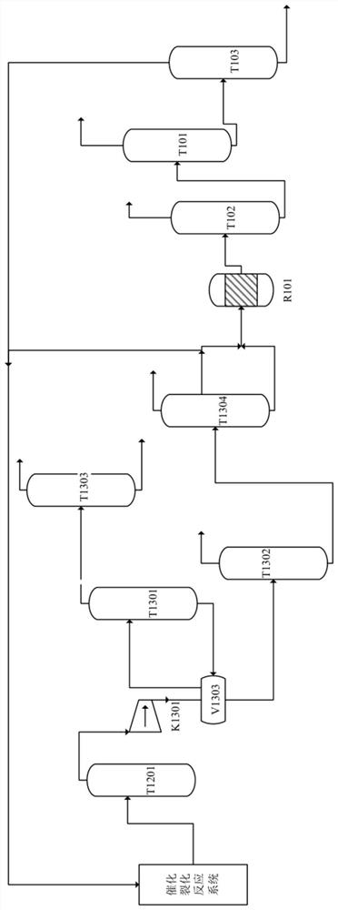
[0003] The gasoline produced by the catalytic cracking unit is sent to the gasoline hydrogenation unit for selective hydrogenation of the whole fraction first, and then qualified gasoline products are obtained through rectification and extraction. With the upgrading of the national gasoline standard, the olefin content in gasoline is strictly controlled, but At present, the content of olefins in the gasoline of the whole plant is relatively high, which affects oil adjustment. It is necessary to reduce the content of olefins in gasoline of the whole plant through technical optimization

Method used


Image

  • Catalytic cracking and gasoline hydrogenation combined method
  • Catalytic cracking and gasoline hydrogenation combined method
  • Catalytic cracking and gasoline hydrogenation combined method

Examples


Embodiment 1

[0072] Adopt the combined technique of catalytic cracking and gasoline hydrogenation described in the technical scheme;

[0073] Wherein, light naphtha and recycled materials are used as feed components as a control group;

[0074] Carry out data accumulation to the operation situation of device before the present invention is implemented, control catalytic cracking raw material is relatively stable, carry out data accumulation again to the device situation after the present invention is implemented stably, compare the difference before and after the present invention is implemented, specific situation is as shown in table 1.1 below:

[0075] Table 1.1 Comparison of device operation data

[0076]

[0077]

[0078] C3+C4 of light naphtha produced by T1304<1%, dry point control <70°C; the present invention conducts PONA analysis on light naphtha, that is, hydrocarbon composition analysis, the results are shown in Table 1.2:

[0079] Table 1.2 PONA analysis results of ligh...

Embodiment 2

[0089] During the stable period of raw material of catalytic cracking unit, data accumulation is carried out on the operation of the device in the implementation stage of the present invention, and then the relevant materials of the present invention are cut out, and data accumulation is carried out again after the operation is stable, and the difference before and after the implementation of the present invention is compared. The specific conditions are as shown in Table 2.1 Show:

[0090] Table 2.1 Comparison of device operation data

[0091]

[0092]

[0093] C3+C4 of the light naphtha produced by T1304<1wt%, dry point control<70°C; the present invention conducts PONA analysis on the light naphtha, that is, hydrocarbon composition analysis, the results are shown in Table 2.2:

[0094] Table 2.2 PONA analysis results of light naphtha

[0095]

[0096] The initial boiling point of the reused material obtained from the T103 weight cutting tower is >40°C, and the fina...


PUM


Abstract

The invention provides a catalytic cracking and gasoline hydrogenation combined method which comprises the following steps: carrying out a catalytic cracking reaction on a catalytic cracking raw material, and sequentially carrying out fractionation, separation, desorption, absorption and stabilization to obtain dry gas, liquefied gas, light naphtha, diesel oil and slurry oil; 60-70 wt% of light naphtha and gasoline are sequentially subjected to a gasoline hydrogenation reaction and gasoline hydrogenation separation, and a delivery material and a recycling material are obtained, wherein the distillation range of the light naphtha controls the content of C3 + C4 to be less than 1wt% and the dry point to be 70 DEG C, the distillation range of the recycled material controls the initial boilingpoint to be more than 40 DEG C and the final boiling point to be 90-101 DEG C; 30%-40% of the light naphtha and the recycled material return to continue the catalytic cracking reaction. According tothe method, 30-40% of light naphtha, a recycled material and a catalytic cracking raw material are subjected to a catalytic cracking reaction together so that the yield of liquefied gas and the content of propylene in the liquefied gas are both increased, and the content of ethylene in dry gas is also obviously increased.

Description

technical field [0001] The invention belongs to the technical field of refining and chemical industry, and in particular relates to a method for combining catalytic cracking and gasoline hydrogenation. Background technique [0002] The main raw materials used in catalytic cracking are atmospheric and vacuum gas oil, coker gas oil, fuel oil, etc., which react under the action of high-temperature catalysts, and obtain dry gas, liquefied gas, gasoline, diesel oil, oil slurry, etc. through fractionation system and absorption stabilization system product. Under the guidance of national policies and the conversion of new and old kinetic energy, the profit margins of gasoline and diesel oil refining units have declined. In recent years, the technical focus has been on optimizing the product distribution of catalytic cracking units and increasing the production of low-carbon olefins, especially the content of propylene in liquefied gas and ethylene in dry gas. . [0003] The gasol...

Claims


Application Information

Patent Timeline
Patent Type & Authority Applications(China)
IPC IPC(8): C10G67/02
CPCC10G67/02C10G2300/4006C10G2300/4012C10G2400/20
Inventor 郝涛远史会兵郭田张成富栾波王耀伟
Owner SHANDONG JINGBO PETROCHEM
Why Eureka
Try Eureka