High-order mode filter

A filter and high-order mode technology, applied in the field of lasers, can solve problems such as the fiber drawing process that needs to be further explored, cannot be solved from the root cause, and affects the quality of the output laser beam, so as to avoid beam quality degradation, easy processing, and integration. high degree of effect

Pending Publication Date: 2020-10-30
NAT UNIV OF DEFENSE TECH
View PDF0 Cites 7 Cited by
  • Summary
  • Abstract
  • Description
  • Claims
  • Application Information

AI Technical Summary

Problems solved by technology

But these methods can not solve the problem from the root
In addition, designing a fiber with a large core diameter that can suppress high-order modes is a long-term task. Although it is theoretically feasible, the fiber drawing process needs to be further explored
Studies have shown that improving LP 01 Mode of photon lifetime or reduced LP 11 The photon lifetime of the mode can increase the mode instability threshold, which can be achieved by bending the fiber or writing the LP 01 High mode reflectivity and LP 11 Fiber Bragg Gratings with Low Mode Reflectivity, Bending Fiber Improves LP 11 mode loss, but the LP 01 The loss of the mode will also increase to a certain extent, which will affect the beam quality of the output laser, and the fiber Bragg grating is mainly used for the cavity mirror of the oscillator, and the situation of the amplifier is limited, so a design that is suitable for both the oscillator and the amplifier Inhibitable LP 11 Mode fiber optic devices are necessary

Method used


Image

  • High-order mode filter
  • High-order mode filter
  • High-order mode filter

Examples


Embodiment 1

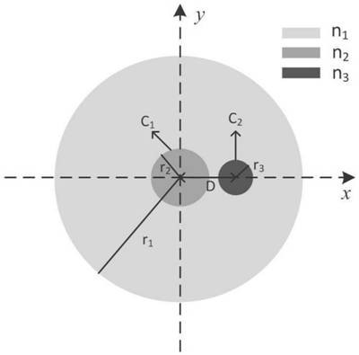
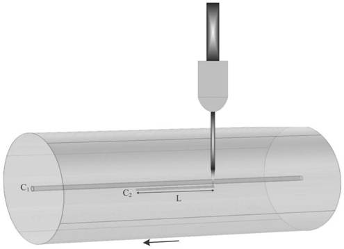
[0045] Such as figure 1 Shown is the structural representation of embodiment 1. High-order mode filters, including large-core fibers, in the core C of large-core fibers 1 The outer cladding is engraved with the x-axis cladding waveguide C 2 , the x-axis cladding waveguide C 2 With a certain length, the x-axis cladding waveguide C 2 The length direction of the fiber is consistent with the length direction of the large core diameter fiber. Core C using large core diameter fiber 1 and the x-axis cladding waveguide C 2 The energy overlap between the respective evanescent fields realizes mode coupling, thereby realizing filtering of high-order modes in the fiber core. The inner cladding radius of the large core fiber is r 1 , in this example r 1 = 200 μm. The core radius of the large core fiber is r 2 , in this example r 2 = 10 μm. x-axis cladding waveguide C 2 has a radius of r 3 , in this example r 3 = 4 μm.

[0046] In order to achieve coupling with ordinary sing...

Embodiment 2

[0057] On the basis of Embodiment 1, the high-order mode filter provided by this embodiment, in the core C of the large-core-diameter optical fiber 1 The outer cladding is engraved with the x-axis cladding waveguide C 2 and y-axis cladding waveguide C 3 . x-axis cladding waveguide C 2 and y-axis cladding waveguide C 3 The length, index of refraction, and spacing from the core are all identical.

[0058] Such as Figure 5 As shown, in the core and x-axis cladding waveguide C 2 and y-axis cladding waveguide C 3 In the case that the pitch of each fiber is 15 μm, a single-mode waveguide with a length of 1.967 mm is written on the cladding in the x-direction and y-direction of the core of the large-core fiber by femtosecond laser direct writing technology. x-axis cladding waveguide C 2 and y-axis cladding waveguide C 3 Parameters such as the length of the fiber core, the distance from the fiber core, and the refractive index must be reasonably designed, and the LP in the f...

Embodiment 3

[0062] This embodiment provides a method for manufacturing a high-order mode filter, including:

[0063] (1) Given a large core diameter fiber, the core diameter, cladding radius and refractive index of the large core diameter fiber are known;

[0064] (2) Determine the parameters of the cladding waveguides to be written, including the number of cladding waveguides and the length of each cladding waveguide, the refractive index of each cladding waveguide, the radius of each cladding waveguide, and each cladding waveguide and fiber core distance.

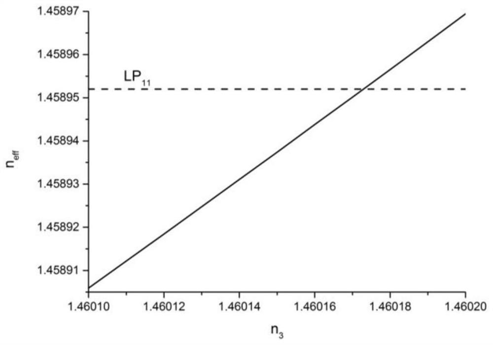
[0065] (2.1) Knowing the cladding radius and refractive index of the optical fiber, establish a single waveguide model, and determine the radius and refractive index range of the cladding waveguide through finite element software calculations, so that it can only transmit the fundamental mode, which needs to meet the cladding waveguide fundamental The effective refractive index of the mode and the core LP 11 The effective refractiv...


PUM

PropertyMeasurementUnit
diameteraaaaaaaaaa

Abstract

The invention provides a high-order mode filter, which comprises an optical fiber, wherein a cladding waveguide is arranged in a cladding on the outer side of a fiber core of the optical fiber, the cladding waveguide has a certain length, and the length direction of the cladding waveguide is consistent with the length direction of the optical fiber. The mode coupling is realized by utilizing the energy overlapping between the evanescent fields of the fiber core and the cladding waveguide, so that the filtering of the high-order mode of the fiber core is realized, and the device has important application value for inhibiting the mode instability effect in a high-power fiber laser and improving the output power of the laser.

Description

technical field [0001] The invention relates to the technical field of lasers, in particular to a high-order mode filter. Background technique [0002] Mode instability is an important limiting factor that restricts the further improvement of the power of high-power large-core fiber lasers. Due to the large core diameter of the fiber used in the laser, it can support LP at the same time 01 Die and LP 11 Mode transmission, the two modes interfere in the fiber core, and the intensity of the interference field presents a periodic distribution along the axis of the fiber. Under certain threshold conditions, due to the photothermal effect, the periodic interference field will cause thermally induced refractive index The long-period grating, whose period is the beat length of the interference, when there is noise or other disturbances in the laser, there is a phase difference between the interference field and the thermally induced long-period grating, and then the long-period g...

Claims


Application Information

Patent Timeline
Patent Type & Authority Applications(China)
IPC IPC(8): G02B6/02H01S3/08
CPCG02B6/02047G02B6/02052G02B6/02342H01S3/08018
Inventor 王泽锋李宏业王蒙饶斌裕田鑫赵晓帆胡琪浩奚小明陈子伦潘志勇王小林许晓军陈金宝
Owner NAT UNIV OF DEFENSE TECH
Why Eureka
Try Eureka