Oil-sludge-water heat treatment separation and recovery system and method

A technology of separation recovery and hydrothermal treatment, applied in water/sludge/sewage treatment, sludge treatment, chemical instruments and methods, etc., can solve problems such as increased load, difficulty in oil and gas recovery, etc., and achieve small footprint and oil-water separation Good effect, short time-consuming effect

Active Publication Date: 2020-11-10
BC P INC CHINA NAT PETROLEUM CORP +1
View PDF8 Cites 0 Cited by
  • Summary
  • Abstract
  • Description
  • Claims
  • Application Information

AI Technical Summary

Problems solved by technology

However, when this method is applied to oily sludge, the steam carries oil, non-condensable gas, cooling water, etc.

Method used


Image

  • Oil-sludge-water heat treatment separation and recovery system and method

Examples


Embodiment 1

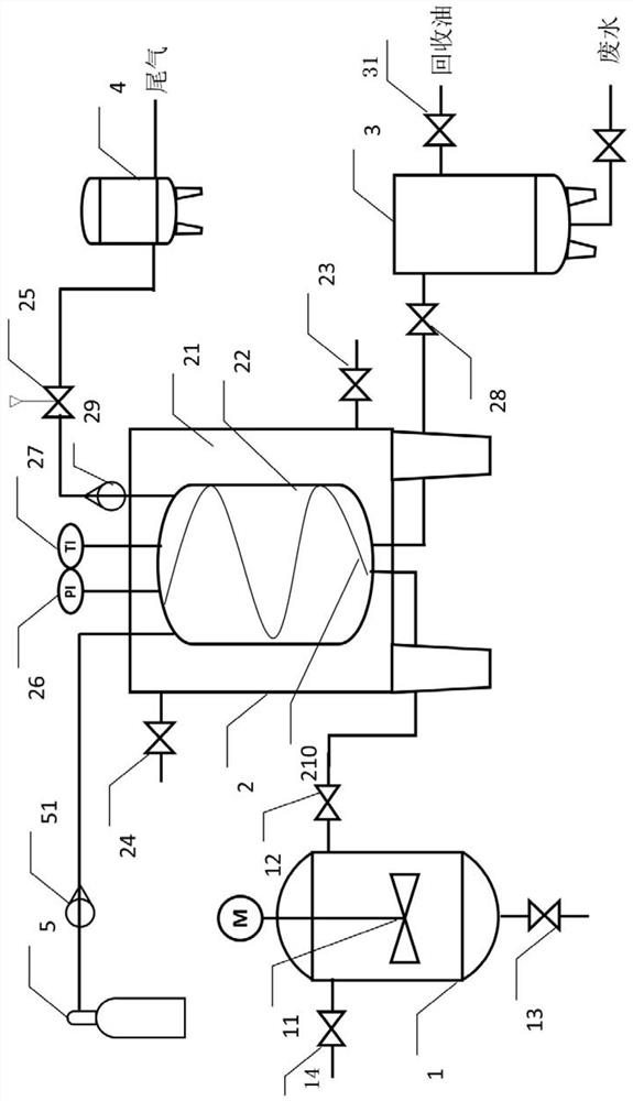
[0049] This embodiment provides a sludge hydrothermal treatment separation and recovery system, the specific structure is as follows figure 1 Shown:

[0050] The system includes: hydrothermal reactor 1, flash condensation tank 2, oil-water separator 3, adsorption tank 4, nitrogen cylinder 5;

[0051] The hydrothermal reactor 1 is a device capable of realizing a hydrothermal reaction. The hydrothermal reactor 1 is provided with a material inlet, a discharge port, and a gas outlet, wherein the discharge port of the hydrothermal reactor 1 is located at the bottom of the hydrothermal reactor and connected to There is a discharge valve 13, and the gas outlet of the hydrothermal reactor 1 is located at the upper part of the hydrothermal reactor; the material inlet of the hydrothermal reactor 1 is located at the upper part of the hydrothermal reactor 1 and is connected with a valve 14; the hydrothermal reactor 1 is provided with Magnetic stirrer 11;

[0052] The flash condensation ...

Embodiment 2

[0056] This embodiment provides a method for separating and recovering oil sludge hydrothermal treatment in fracturing flowback fluid using the oil sludge hydrothermal treatment separation and recovery system provided in Example 1, specifically as follows:

[0057] 1) 500 g of scum oil sludge (moisture content 80-85%) of a certain oil production plant in Xinjiang Oilfield is injected into the hydrothermal reactor 1 from the material inlet of the hydrothermal reactor 1, while stirring (the magnetic stirrer 11 is running) Heating to make the above-mentioned scum and oil sludge undergo a hydrothermal reaction at 120-180°C and 0.2-1.0Mpa for 20-50min, wherein the heating is electric heating, and the stirring speed is 100-300r / min;

[0058] 2) Stop heating the hydrothermal reactor 1, keep the magnetic stirrer 11 to continue running, close the exhaust valve 25 at the top of the flash condensation tank 2 and the drain valve 28 at the bottom, and open the exhaust valve cooling water in...

Embodiment 3

[0064] This embodiment provides a method for separating and recovering oil sludge hydrothermal treatment in fracturing flowback fluid using the oil sludge hydrothermal treatment separation and recovery system provided in Example 1, specifically as follows:

[0065] 1) 500 g of scum oil sludge (moisture content 75-80%) of a certain oil production plant in Xinjiang Oilfield is injected into the hydrothermal reactor 1 from the material inlet of the hydrothermal reactor 1, and 0.45- 1.45MPa, 148-197°C saturated water vapor and stirring the scum and sludge (magnetic stirrer 11 operation) makes the scum and sludge undergo hydrothermal reaction, the hydrothermal reaction time is 10-40min, the stirring speed 100-300r / min;

[0066] 2) Stop heating the hydrothermal reactor 1, keep the magnetic stirrer 11 to continue running, close the exhaust valve 25 at the top of the flash condensation tank 2 and the drain valve 28 at the bottom, and open the exhaust valve cooling water inlet valve 23...


PUM

PropertyMeasurementUnit
Densityaaaaaaaaaa

Abstract

The invention provides an oil sludge water heat treatment separation and recovery system and method. The system comprises a hydrothermal reactor, a flash condensation tank and an oil-water separator,wherein the hydrothermal reactor is provided with a material inlet, a discharge port and a gas outlet, the discharge port of the hydrothermal reactor is located at the lower part of the hydrothermal reactor, and the gas outlet of the hydrothermal reactor is located at the upper part of the hydrothermal reactor; the flash condensation tank is provided with a material inlet, a liquid outlet and a gas outlet; a liquid outlet of the flash condensation tank is positioned at the lower part of the flash condensation tank; a gas outlet of the flash condensation tank is positioned at the upper part ofthe flash condensation tank; the oil-water separator is provided with a material inlet, a water phase outlet and an oil phase outlet; a gas outlet of the hydrothermal reactor is connected with a material inlet of the flash evaporation condensation tank, and a liquid outlet of the flash evaporation condensation tank is connected with a material inlet of the oil-water separator. The system is suitable for heat treatment separation and recovery of oily sludge water, and can effectively realize separation of water, oil and solid-phase residues in oily sludge.

Description

technical field [0001] The invention belongs to the technical field of environmental protection in the petroleum and petrochemical industry, and in particular relates to an oil sludge hydrothermal treatment separation and recovery system and method, in particular to a high water content oil sludge hydrothermal treatment gas-liquid condensation, rapid separation and recovery device and method. Background technique [0002] At a certain temperature and pressure (100°C, above 0.101MPa), heat high-water sludge (referred to as sludge) in a closed container, and under the action of a catalyst, the sludge will undergo floc / colloid cracking, solid dissolution, and organic matter. A series of physical and chemical reactions such as hydrolysis and cracking of macromolecular organic matter, so as to realize the separation of oil, water and mud in sludge. In addition, during the hydrothermal reaction of oil sludge, a large amount of small molecular organic matter will be generated due t...

Claims


Application Information

Patent Timeline
IPC IPC(8): C02F11/00C10G1/02
CPCC02F11/00C10G1/02
Inventor 仝坤张哲娜谢加才李慧敏张娜娜谢水祥周龙涛张明栋李树森
Owner BC P INC CHINA NAT PETROLEUM CORP
Why Eureka
Try Eureka