
Cleaning equipment for refractory material production and using method thereof

A technology for cleaning equipment and refractory materials, which is applied in the directions of cleaning methods, cleaning methods and utensils, chemical instruments and methods using liquids, etc., which can solve the problems of increased cleaning costs, low cleaning efficiency, large dust impurities, etc., to save labor intensity. , waste reduction, multi-functional effect

Active Publication Date: 2020-11-17
山东嘉岳新材料有限公司
View PDF8 Cites 1 Cited by
  • Summary
  • Abstract
  • Description
  • Claims
  • Application Information

AI Technical Summary

Problems solved by technology

[0003] The production process of manufacturing ordinary refractories generally includes calcination of raw materials, selection of raw materials, crushing, batching, mixing, trapping, molding, drying, firing and other processes, but the current refractory factories often purchase calcined cooked Therefore, the calcination of raw materials is no longer considered by ordinary refractory manufacturers. The crushing of raw materials is the first process of refractory production. At present, most of the refractory materials are directly transported into the raw materials when they are produced and processed. The raw material ore will not be pre-cleaned in the crusher for crushing. This method has the following defects: 1. Due to the characteristics of the raw material, large dust and impurities will be accumulated during the long-term storage and transportation process. When the raw material is in When crushing, a large amount of dust and impurities will be produced, which will not only cause certain ambient air pollution, but also cause certain physical damage to workers who often participate in production and processing.
2. Since there is no pre-cleaning before crushing, a large amount of stains and impurities will be produced during crushing, which will have a certain impact on the production quality of refractory materials in the later stage
3. Generally, when pre-cleaning raw materials, it is divided into multiple steps and pre-cleaned on different equipment, which is relatively troublesome and increases the cleaning cost. The cleaning efficiency is relatively low, and the cleaning effect is not ideal.

Method used


Image

  • Cleaning equipment for refractory material production and using method thereof
  • Cleaning equipment for refractory material production and using method thereof
  • Cleaning equipment for refractory material production and using method thereof

Examples


Embodiment 1

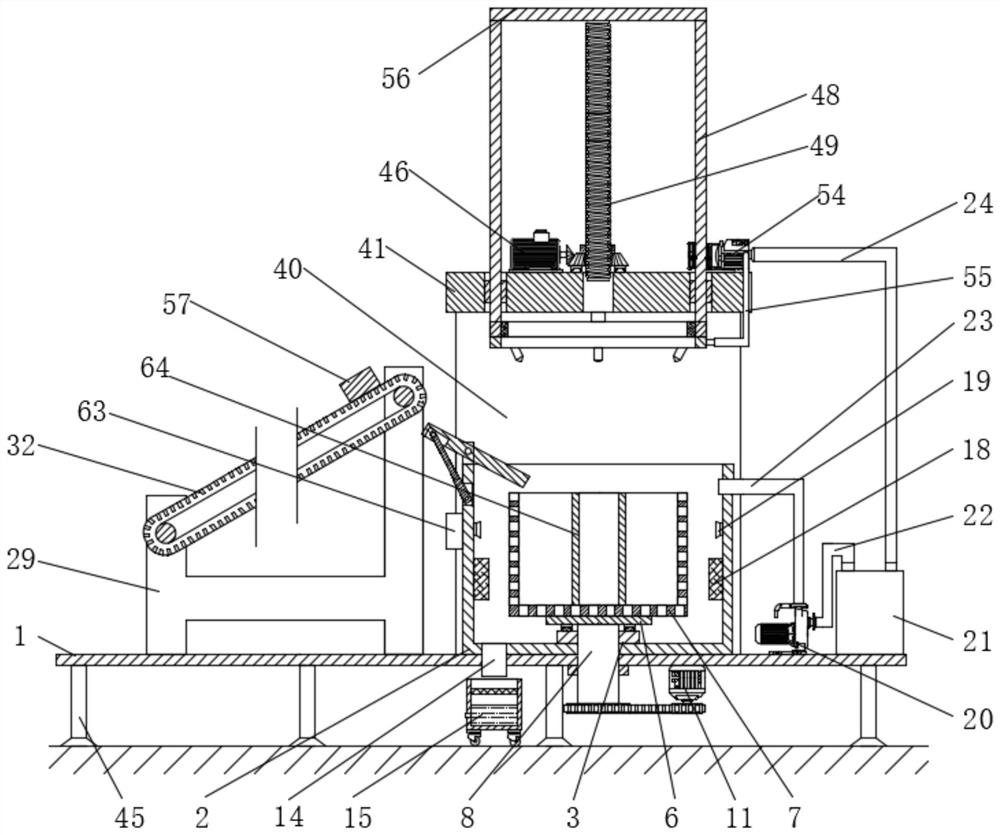
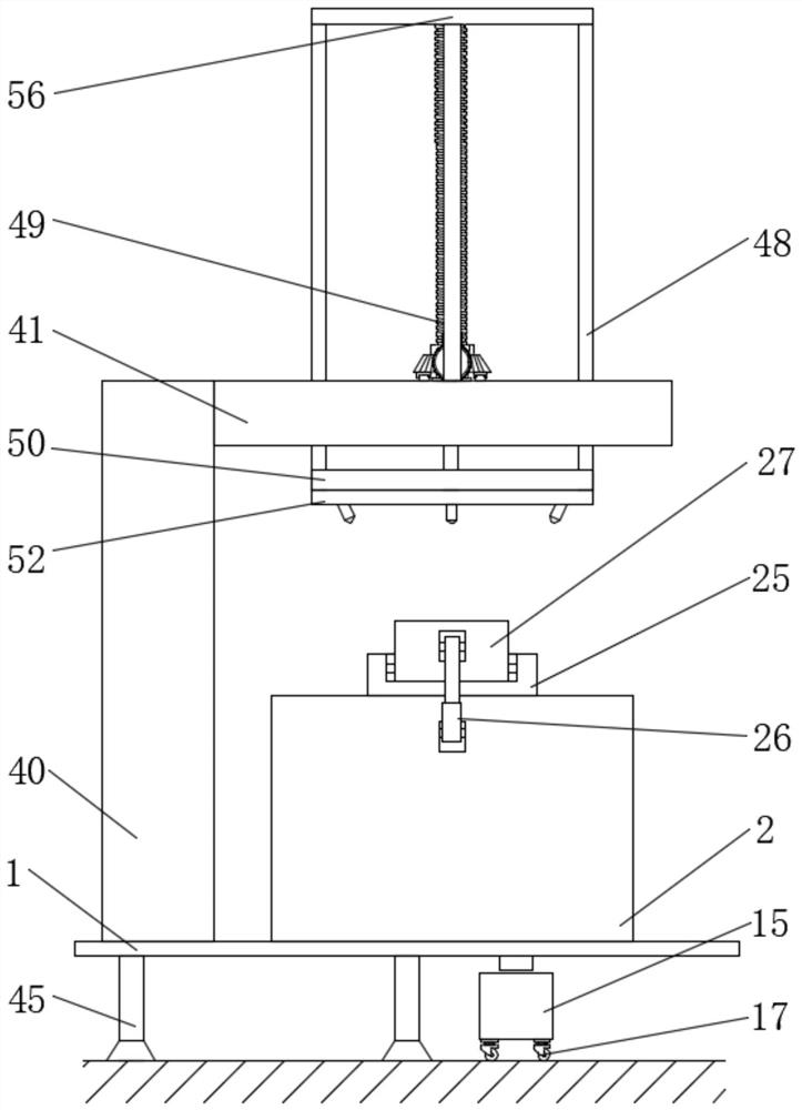
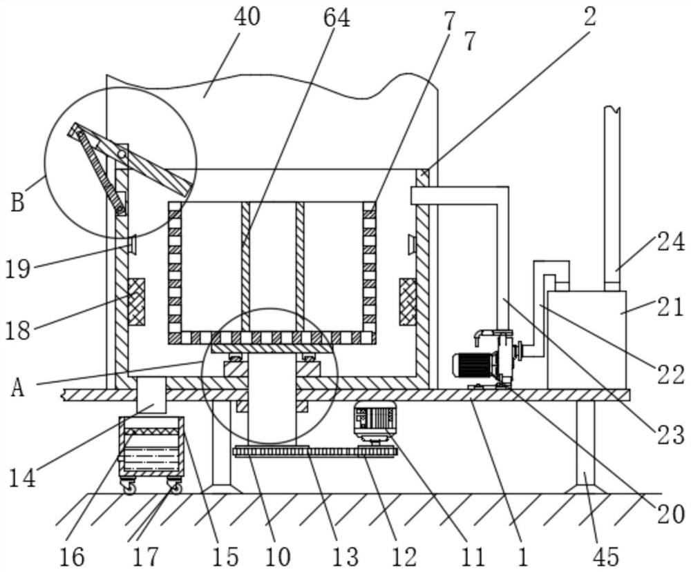
[0043] Embodiment one: if Figure 1-11 As shown, a cleaning device for refractory production includes a workbench 1, a cleaning bucket 2 is fixedly connected to the top of the workbench 1, a fixing plate 3 is fixedly connected to the inner wall of the bottom of the cleaning bucket 2, and the top of the fixing plate 3 slides Connected with a rotating plate 6, the top of the rotating plate 6 is fixedly connected with a hollow metal frame 7, the bottom inner wall of the hollow metal frame 7 is fixedly connected with a drum 64, and the bottom inner wall of the cleaning bucket 2 is rotatably connected with a rotating shaft 8. The top runs through the fixed plate 3 and is fixedly connected with the bottom of the rotating plate 6. The bottom end of the rotating shaft 8 runs through the workbench 1 and is fixedly connected with the first pulley 10. The bottom of the workbench 1 is fixedly connected with a rotating motor 11. The output shaft is fixedly connected with a second pulley 12...

Embodiment 2

[0056] Embodiment two: if Figure 12-15 As shown, a cleaning device for refractory production, the difference between this embodiment and Embodiment 1 is that: the center of the bottom of the hollow metal frame 7 is fixedly connected with a cross plate 58, and the center of the top of the rotating plate 6 is provided with a cross Groove 59, the cross plate 58 is embedded in the cross groove 59, when cleaning is finished, the hollow metal frame 7 in the cleaning bucket 2 can be proposed from the rotating plate 6, and the raw material 57 is taken out, which is simple and convenient.

[0057] Working principle: Place the raw material 57 on the top of the conveyor belt 32, start the drive motor 37, the drive motor 37 drives the fourth synchronous wheel 38 to rotate, and the fourth synchronous wheel 38 drives the second synchronous belt 39 and the first synchronous belt 36 respectively. A synchronous wheel 33 and the second synchronous wheel 34 rotate, and then can drive the transm...


PUM


Abstract

The invention discloses cleaning equipment for refractory material production. The cleaning equipment for the refractory material production comprises a workbench, a cleaning barrel is fixedly connected to the top of the workbench, a fixed plate is fixedly connected to the inner wall of the bottom of the cleaning barrel, a rotating plate is slidably connected to the top of the fixed plate, a hollowed-out metal frame is fixedly connected to the top of the rotating plate, a circular barrel is fixedly connected to the inner wall of the bottom of the hollowed-out metal frame, a rotating shaft is rotationally connected to the inner wall of the bottom of the cleaning barrel, and the top end of the rotating shaft penetrates through the fixed plate and fixedly connected with the bottom of the rotating plate. The cleaning equipment is simple in structure, capable of integrating first-stage simple cleaning, second-stage fine cleaning, flushing, water throwing and drying, simple, practical, a machine being used for multiple purposes is achieved, in addition, a waste water collecting box and a waste water filtering net are further arranged, the waste water can be collected after being filtered, the effects of waste water collecting and recycling can be achieved, the cleaning and drying efficiency is improved, water resources can be further saved, and the cleaning cost is reduced.

Description

technical field [0001] The invention relates to the technical field of cleaning equipment, in particular to a cleaning equipment used for refractory production and a usage method thereof. Background technique [0002] Refractories are a type of inorganic non-metallic materials with a refractoriness not lower than 1580°C. Refractoriness refers to the Celsius temperature at which a refractory conical sample can resist high temperature without softening and melting without load. However, it is not possible to fully describe refractory materials only by the definition of refractoriness, and 1580°C is not absolute. It is now defined as a material whose physical and chemical properties allow it to be used in a high temperature environment is called a refractory material. Refractory materials are widely used in metallurgy, chemical industry, petroleum, machinery manufacturing, silicate, power and other industrial fields, and are used in the largest amount in the metallurgical ind...

Claims


Application Information

Patent Timeline
IPC IPC(8): B08B3/02B08B3/10B08B3/12B08B3/14F26B23/06
CPCB08B3/022B08B3/047B08B3/10B08B3/123B08B3/14B08B2203/007F26B23/06
Inventor 陈笑雪其他发明人请求不公开姓名
Owner 山东嘉岳新材料有限公司
Learn More