
Dielectric ceramic composition and ceramic electronic component

A technology of dielectric ceramics and composites, which is applied to fixed capacitance components, ceramics, electrical components, etc., and can solve problems such as low relative permittivity, inability to obtain high-capacity capacitors, and degradation of characteristics

Active Publication Date: 2020-11-17
SHOEI CHEM IND CO LTD
View PDF19 Cites 1 Cited by
  • Summary
  • Abstract
  • Description
  • Claims
  • Application Information

AI Technical Summary

Problems solved by technology

However, in an electronic component having a dielectric layer made of a paraelectric, the relative permittivity of the ceramic composition is low, and a high-capacity capacitor cannot be obtained.
[0004] Barium titanate (BaTiO) known as a representative ceramic composition for ceramic capacitors 3 ), although it has a high relative permittivity, the relative permittivity has a peak at the characteristic temperature called the ferroelectric transition temperature, and when it becomes 120°C or higher, the characteristics drop rapidly

Method used


Image

  • Dielectric ceramic composition and ceramic electronic component
  • Dielectric ceramic composition and ceramic electronic component
  • Dielectric ceramic composition and ceramic electronic component

Examples


Embodiment

[0169] First, a confirmation test was carried out on regulation of the content of the first component and the effect of adding Mn oxide (reference samples 1 to 90 and reference samples 91 to 107).

reference example 1

[0171] (1) Preparation of Dielectric Ceramic Composition Reference Samples 1-90

[0172] As a starting material for the first component, CaCO 3 , SrCO 3 、BaCO 3 、TiO 2 , ZrO 2 , SnO 2 , Nb 2 o 5 、 Ta 2 o 5 , V 2 o 5 The respective powders were weighed so that the ratios shown in Table 1, Table 3, and Table 5 were obtained in terms of oxides, and wet mixing was performed for 20 hours using pure water using a ball mill.

[0173] Next, each of the obtained mixtures was dried at 100° C., then calcined at 750° C. to 900° C. for 3 hours in the air, and finely pulverized by a ball mill again to obtain a dielectric raw material for the first component.

[0174] In addition, as a second component, MnCO was weighed separately 3 18.2mg, MgO 32mg, SiO 2 58.6mg, Y 2 o 3 89.5 mg, and these mixed substances were prepared as raw materials for the second component. Wherein, in the reference sample 43, the raw materials for the second component only use SiO 2 MnCO 3 , MgO an...

reference example 2

[0213] The first component raw material was weighed so that it had the composition shown in Table 7 in terms of oxides, and MnCO as the second component raw material was weighed. 3 and SiO 2 Except weighing so as to have the composition shown in Table 7 in terms of oxides, reference samples 91 to 107 were prepared in the same manner as in Reference Example 1, and disc-shaped ceramic capacitors corresponding to the respective samples were obtained. .

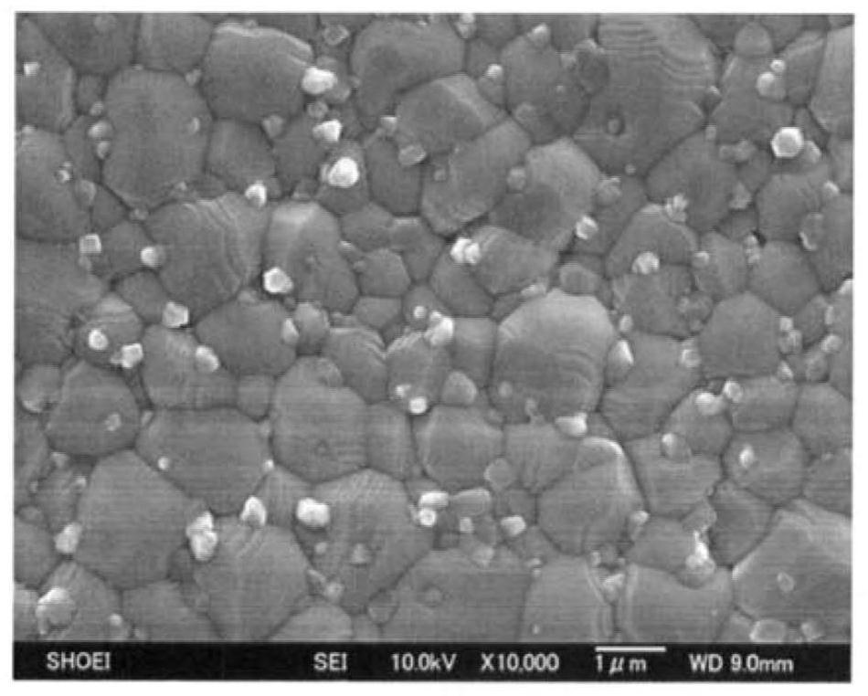
[0214] Thereafter, the particle size, crystal phase, relative permittivity, capacitance change rate, and dielectric loss (tan δ) were measured in the same manner as in Reference Example 1, and the results are shown in Table 8.

[0215] From these results, it can be seen that relative to the total mass of the first component in terms of oxides, in the case of samples whose Mn content in terms of MnO as the second component is 3.500% by mass or less, the relative permittivity and capacitance change Good results were obtained in t...


PUM

PropertyMeasurementUnit
electrical resistanceaaaaaaaaaa
particle sizeaaaaaaaaaa
diameteraaaaaaaaaa

Abstract

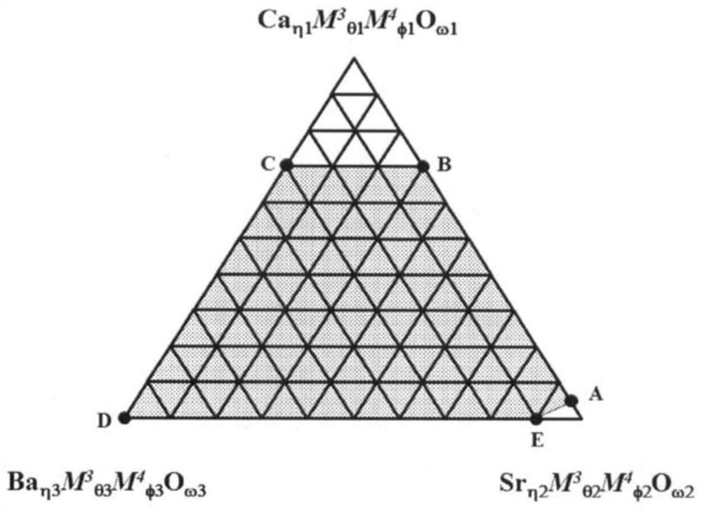
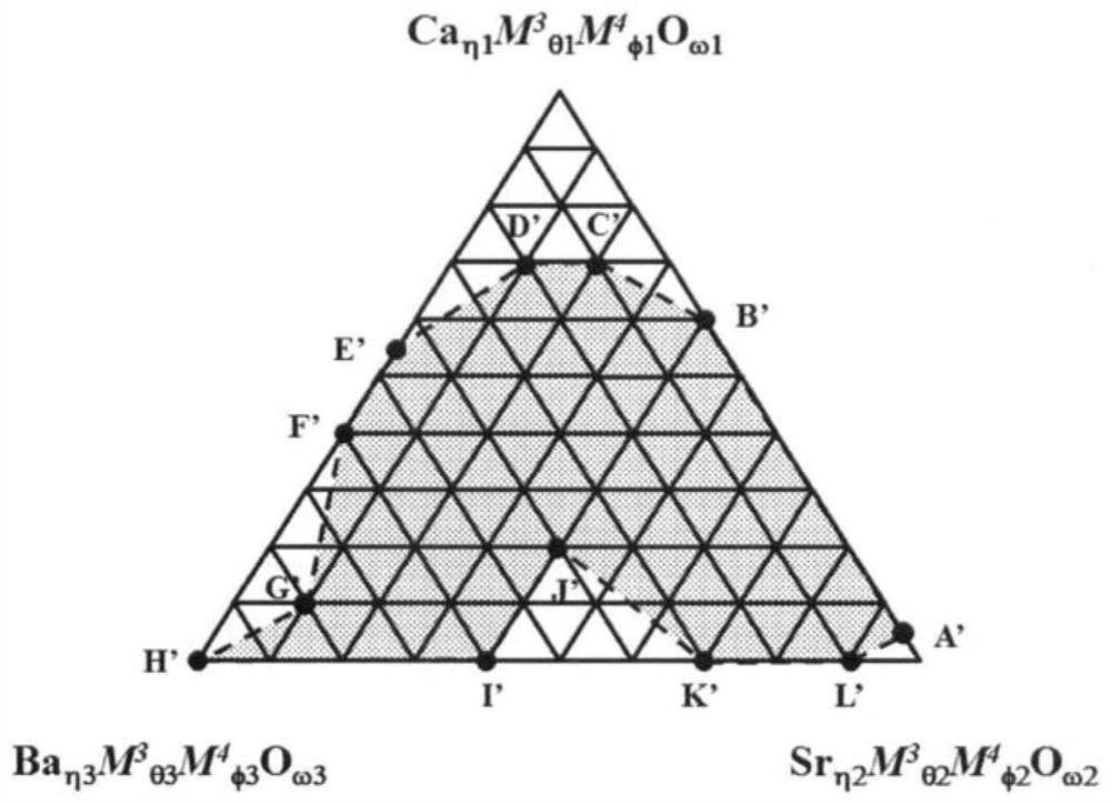
A dielectric ceramic composition comprises a first ingredient and a second ingredient. The first ingredient comprises 0.00 to 35.85% by mole of an oxide of Ca, 0.00 to 47.12% by mole of an oxide of Sr, 0.00 to 51.22% by mole of an oxide of Ba, 0.00 to 17.36% by mole of an oxide of Ti, 0.00 to 17.36% by mole of an oxide of Zr, 0.00 to 2.60% by mole of an oxide of Sn, 0.00 to 35.32% by mole of an oxide of Nb, 0.00 to 35.32% by mole of an oxide of Ta, and 0.00 to 2.65% by mole of an oxide of V. As the second ingredient, the dielectric ceramic composition comprises at least 0.005 to 3.500% by massof an oxide of Mn (a); and 0.080 to 20.000% by mass of an oxide of Cu and / or 0.300 to 45.000% by mass of an oxide of Ru (b). According to the present invention, the dielectric ceramic composition canbe provided, wherein changes in the electrostatic capacity are small even under a high-temperature environment, dielectric losses at 25 DEG C and 200 DEG C are small, and the insulation resistance value under a high-temperature environment is high.

Description

technical field [0001] The present invention relates to a dielectric ceramic composition and a ceramic electronic component using the dielectric ceramic composition as a dielectric layer. Background technique [0002] In recent years, the demand for electronic components operating in a high-temperature environment exceeding 150° C. has been increasing year by year for devices installed in the engine compartment of automobiles and other devices in extremely severe temperature environments. Especially in the automotive market in recent years, in order to improve safety and environmental performance, the electronic control of each function has been rapidly promoted, and the installation rate of electronic equipment has increased. Among them, electronic devices installed in the engine compartment are exposed to extremely severe temperature environments, and therefore high heat resistance is required in addition to high reliability in electronic components. [0003] Conventional...

Claims


Application Information

Patent Timeline
Patent Type & Authority Applications(China)
IPC IPC(8): C04B35/495C04B35/499H01B3/12H01G4/30
CPCC04B35/495H01G4/30H01B3/12H01G4/1227H01G4/1254H01G4/1245C04B35/62685C04B35/6263C04B2235/3206C04B2235/3262C04B2235/3281C04B2235/3231C04B2235/442C04B2235/3418C04B2235/604C04B2235/6562C04B2235/6567C04B2235/6588C04B2235/6582C04B2235/3208C04B2235/3213C04B2235/3215C04B2235/3232C04B2235/3293B32B18/00C04B2237/346C04B2237/348C04B2237/405C04B2237/407H01G4/1209C04B35/499H01G4/008C04B2235/3236C04B2235/3239C04B2235/3244C04B2235/3251C04B2235/3284
Inventor 野村武史佐佐木由香里
Owner SHOEI CHEM IND CO LTD
Learn More