Multi-primary-color laser array side-entry type light homogenizing surface light source of liquid crystal display

A liquid crystal display and multi-primary color technology, applied in the field of laser backlight, can solve the problems of uneven intensity distribution, uneven brightness and darkness of the blurred screen, and low brightness

Pending Publication Date: 2020-12-04
北京熔煜科技发展有限公司
View PDF3 Cites 2 Cited by
  • Summary
  • Abstract
  • Description
  • Claims
  • Application Information

AI Technical Summary

Problems solved by technology

Since the three-color lasers are directly incident on the light guide plate, the distance between the lasers is too far, the intensity distribution of the red, green and blue three-color lasers is uneven, and white light cannot be synthesized, resulting in blurred screen phenomenon and uneven brightness and darkness of the screen, which cannot meet the normal use requirements of liquid crystal displays.
None of these existing patent solutions can solve the practical problems of color spots, color bands, uneven distribution of light field and low brightness caused by the mismatch between the visible light end-emitting laser and the optical system of the existing side-entry LED liquid crystal display.

Method used


Image

  • Multi-primary-color laser array side-entry type light homogenizing surface light source of liquid crystal display
  • Multi-primary-color laser array side-entry type light homogenizing surface light source of liquid crystal display
  • Multi-primary-color laser array side-entry type light homogenizing surface light source of liquid crystal display

Examples


Embodiment 1

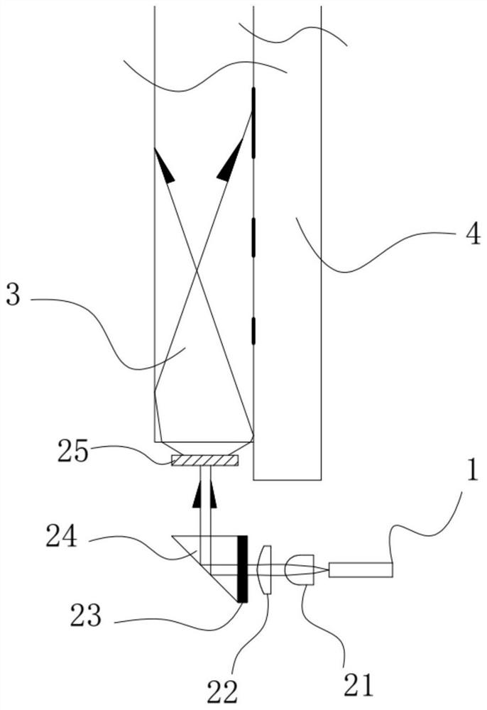
[0036] as attached image 3 As shown, this embodiment discloses a condition and a backlight source for converting a Gaussian laser beam emitted by an end-emitting laser into a top-hat laser beam. Specifically, the end-emitting visible light laser 1 is arranged perpendicular to the light-emitting surface of the light guide plate 3 . A Gaussian laser beam fast-axis compression cylindrical lens 21 and a Gaussian laser beam collimating aspheric mirror 22 are installed at the light exit of the end-emitting visible light laser 1 to focus the Gaussian laser beam into a laser spot with a diameter less than 1.5mm. The laser spot is incident on the refractive micro-optical beam expander 23 arranged on the right-angled surface of the rectangular prism 24 . The refractive micro-optical beam expander 23 expands the laser spot into a flat-top line beam with a uniformity greater than 60%. The length of the flat top-shaped line beam is parallel to the long side or wide side of the light gui...

Embodiment 2

[0039] as attached Figure 4 As shown, this embodiment discloses a condition and a backlight source structure for converting a Gaussian laser beam emitted by an end-emitting laser into a top-hat laser beam.

[0040] Specifically, the end-emitting visible light laser 1 is arranged perpendicular to the light-incident surface of the side of the light guide plate 3 . A Gaussian laser beam collimator 26 is installed at the light exit of the end-emitting visible light laser 1 to focus the Gaussian laser beam into a laser spot with a divergence angle of 4°. The laser spot is incident on the micro-cylindrical lens array 27 , and the arrangement direction of the micro-cylindrical lens array 27 is that the length of the micro-cylindrical lens is parallel to the thickness direction of the light guide plate 3 . After the laser spot passes through the micro-cylindrical lens array 27, it is expanded into an approximately flat-top laser line spot with a fast-axis divergence angle of 150° an...

Embodiment 3

[0044] as attached Figure 5 As shown, this embodiment discloses a liquid crystal display backlight homogenization structure using a chip-type vertical cavity laser (VCSEL) array as a light source.

[0045] The patch-type vertical cavity blue laser 11 , the patch-type vertical cavity red laser 12 and the patch-type vertical cavity green laser 13 together constitute a backlight source for a patch-type three-primary-color laser liquid crystal display.

[0046] The central wavelength of the three-color vertical cavity visible light laser is between 400-490nm for blue light, 500-580nm for green light, and 600-680nm for red light, and the spectral half-peak width of the three-color vertical cavity visible light laser is less than 10nm.

[0047] Specifically, several patch-type vertical cavity blue lasers 11, several patch-type vertical cavity red lasers 12, and several patch-type vertical cavity green lasers 13 are alternately arranged on the heat-conducting PCB board. A Gaussian ...


PUM

PropertyMeasurementUnit
wavelengthaaaaaaaaaa

Abstract

The invention discloses a multi-primary-color laser array side-entry light homogenizing surface light source of a liquid crystal display, and belongs to the technical field of laser optical display. The light homogenizing surface light source comprises a visible light semiconductor laser, a light beam shaping device and a liquid crystal display light guide plate, the visible light semiconductor laser forms a multi-primary-color laser array in the backlight source of the side-entry liquid crystal laser display, and laser beams with the light intensity in Gaussian distribution emitted by the multi-primary-color laser array are converted into laser beams with the light intensity in flat-topped distribution by the beam shaping device and then enter the light guide plate. And the light intensity distribution uniformity of the flat-topped laser beams on the light incident surface of the light guide plate is greater than 50%. According to the invention, color spots, color blocks, bright and dark stripes and non-uniform color temperature caused by non-overlapping of the multi-primary-color laser array side in the light guide plate of the liquid crystal display can be eliminated, so that auniformly distributed white light field is obtained.

Description

technical field [0001] The invention relates to a laser backlight source of a liquid crystal display, in particular to a multi-primary color laser array side entry type liquid crystal display backlight uniform light and color combination optical assembly. Background technique [0002] The optical system of the existing liquid crystal display is designed for the surface light source with LED as the basic component of light emission, and has been very mature. [0003] The advantages of LED light sources are that the light energy is approximately uniform; the shape and size of the light-emitting area can be changed through semiconductor processing technology; and uniform white light can be formed. The above advantages determine that LEDs can be made into patch lamp bead-type narrow strip surface light sources composed of a large number of low-power light spots, so they are widely used as backlight sources for side-entry liquid crystal displays. [0004] However, a liquid cryst...

Claims


Application Information

Patent Timeline
Patent Type & Authority Applications(China)
IPC IPC(8): G02F1/13357G02B27/09G02B6/00
CPCG02B6/0023G02B6/003G02B6/0031G02B6/0066G02B27/0927G02B27/0938G02B27/0944G02B27/095G02B27/0955G02B27/0961G02B27/0966G02B27/0972G02B27/0977G02B27/0983G02F1/133606
Inventor 许江珂许江临杨志永张大雷陈杰
Owner 北京熔煜科技发展有限公司
Why Eureka
Try Eureka