Supercharge Your Innovation With Domain-Expert AI Agents!

High-temperature-resistant and high-pressure-resistant energetic material rod structure and application thereof

A high temperature resistant, material rod technology, applied in the fields of production fluids, wellbore/well components, earthwork drilling, etc., can solve the problems of reducing the cementation position, reducing the success rate of controllable shock wave operation, etc., reducing the cementing position and widening the application performance, improve stability

Pending Publication Date: 2020-12-11
CHINA NAT OFFSHORE OIL CORP +1
View PDF10 Cites 1 Cited by
  • Summary
  • Abstract
  • Description
  • Claims
  • Application Information

AI Technical Summary

Problems solved by technology

[0004] The invention overcomes the deficiencies in the prior art. Due to local temperature rise and local pressurization, problems such as cracking and deformation of the shell of the energetic material rod, failure of the seal between the metal wire and the shell and water ingress occur, reducing the controllable The success rate of the shock wave operation provides a high temperature and high pressure resistant energetic material rod structure and its application. The ceramic tube body and ceramic plug with one end closed not only ensure the high temperature resistance of the energetic material rod shell, but also reduce the The bonding position is reduced, and the possibility of water entering the bonding surface is reduced. The riveting structure of the metal wire at both ends of the energetic material rod uses two methods of external force boosting and bonding to ensure the tightness of the metal wire.

Method used


Image

  • High-temperature-resistant and high-pressure-resistant energetic material rod structure and application thereof

Examples


Embodiment 1

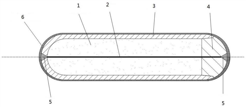
[0021] A high temperature and high pressure resistant energetic material rod structure, including a high temperature resistant shell, a powdery energetic material 1, a metal wire 2, a fixing member 5 and a pressure-resistant coating 6,

[0022] The high temperature resistant shell includes a U-shaped pipe body 3 and a plug 4. The U-shaped pipe body 3 adopts a hollow cylindrical structure with one end open and the other end closed. One end of the plug 4 is a hemispherical compression structure, and the other end of the plug 4 is It is a cylindrical structure matching the open end of the U-shaped pipe body 3. The U-shaped pipe body 3 is connected to the plug 4 by bonding, and the closed end of the U-shaped pipe body 3 and the center of the plug 4 There is a fixing hole for fixing the metal wire 2 at the center. The first and last ends of the metal wire 2 are respectively fixed in the fixing hole by the fixing piece 5. The energetic material 1 is coated with a pressure-resistant ...

Embodiment 2

[0024] On the basis of the first embodiment, the U-shaped pipe body 3 and the plug 4 are made of aluminum oxide high-temperature ceramic material, and the high-temperature ceramic material has a temperature resistance of 150°C.

[0025] The metal wire 2 is made of metal tungsten, metal tantalum or metal copper, and the diameter of the metal wire 2 is 300-500 μm.

[0026] The powdery energetic material 1 includes strong oxidant, nitrocellulose, nitrate, etc., the particle size of the powdery energetic material 1 is 20-200 μm, and the powdery energetic material 1 is mixed by a wet method to ensure dispersion and optimal filling density.

[0027] The pressure-resistant coating 6 adopts multi-walled carbon nanotube coating.

[0028] During assembly, the first end of the metal wire 2 is first riveted to the fixing hole in the center of the hemispherical closed end of the U-shaped tube body 3, and reinforced with a sealant, and then the powdery energetic material 1 is filled accord...

Embodiment 3

[0030] On the basis of Example 2, an energetic material rod structure resistant to high temperature and high pressure is applied in a controllable shock wave device under high temperature and high pressure conditions. The energetic material rod structure needs to be driven by a driving source with a pulse power of more than 800J.


PUM

PropertyMeasurementUnit
Diameteraaaaaaaaaa
Particle sizeaaaaaaaaaa
Diameteraaaaaaaaaa

Abstract

The invention provides a high-temperature-resistant and high-pressure-resistant energetic material rod structure and application thereof. A high-temperature-resistant shell comprises a U-shaped pipe body and a plug, wherein the U-shaped pipe body is of a hollow cylindrical structure with one open end and one closed end; one end of the plug is of a hemispherical pressure-resistant structure, and the other end of the plug is of a cylindrical structure matched with the open end of the U-shaped pipe body; the U-shaped pipe body is connected with the plug in a bonding mode, fixing holes used for fixing a metal wire are formed in the central positions of the closed end of the U-shaped pipe body and the plug, and the head end and the tail end of the metal wire are fixed in the fixing holes through fixing pieces correspondingly; and a cavity of the U-shaped pipe body is evenly filled with powdery energetic materials, and the outer side of the U-shaped pipe body and the outer side of the plug are coated with pressure-resistant coatings. The ceramic pipe body with one closed end and the ceramic plug are adopted, so that the high-temperature resistance of the shell of the energetic material rod is guaranteed, the adhesion bonding position is reduced, and the possibility that water enters an adhesion bonding face is reduced.

Description

technical field [0001] The invention relates to the technical field of controllable shock wave application devices, and more specifically relates to a high temperature and high pressure resistant energetic material rod structure and its application. Background technique [0002] One of the key components of the controllable shock wave technology applied to the stimulation of production and injection of oil and water wells is the rod of energetic material coated on the metal wire. Driven by the plasma generated by the electric explosion of the metal wire, the powdery energetic material in the energetic material rod can form a stable detonation, form a local strong pulse shock wave in the water, act on various reservoirs, and realize oil-water well detonation. Plugging, shale gas, coalbed methane reservoir permeability enhancement, in order to achieve the purpose of increasing production and efficient mining. [0003] In the current controllable shock wave generation technolo...

Claims


Application Information

Patent Timeline
IPC IPC(8): E21B33/13E21B28/00E21B43/16
CPCE21B33/13E21B28/00E21B43/16
Inventor 李昂杨万有黄波郑春峰苏作飞尹莎莎赵景辉汤俊萍
Owner CHINA NAT OFFSHORE OIL CORP
Features
  • R&D
  • Intellectual Property
  • Life Sciences
  • Materials
  • Tech Scout
  • Unparalleled Data Quality
  • Higher Quality Content
  • 60% Fewer Hallucinations
Learn More