
Cover plate type packaging structure and method for perovskite solar cell

A technology of solar cells and packaging structures, applied in circuits, photovoltaic power generation, electrical components, etc., can solve the problems of complicated packaging methods and high costs, achieve excellent mechanical properties and weather resistance, fully respond, and improve the effect of system strength

Pending Publication Date: 2020-12-22
SHAANXI NORMAL UNIV
View PDF0 Cites 0 Cited by
  • Summary
  • Abstract
  • Description
  • Claims
  • Application Information

AI Technical Summary

Problems solved by technology

[0004] The purpose of the present invention is to overcome the above-mentioned shortcoming of the prior art, and the purpose of the present invention is to overcome the shortcoming of the prior packaging technology, provide a kind of cover-type packaging structure and method of the perovskite solar cell, to prevent water vapor in the air from The influence of each functional layer of perovskite solar cell devices, while solving the problems of complexity and high cost of existing packaging methods

Method used


Image

  • Cover plate type packaging structure and method for perovskite solar cell
  • Cover plate type packaging structure and method for perovskite solar cell
  • Cover plate type packaging structure and method for perovskite solar cell

Examples


Embodiment 1

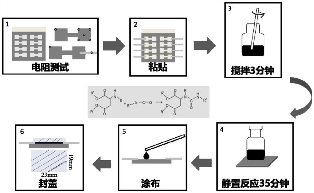
[0066]Step 1, the determination of the equivalent electrode resistance on the surface of the perovskite solar cell; use a compressed air spray gun with a working pressure of 0.4MPa to clean the surface of the prepared perovskite solar cell device, and use a multimeter to measure by the five-point sampling method The initial resistance R0 of each group of equivalent electrodes, after the measurement is completed, the surface is cleaned again.

[0067] Step 2, lead out the equivalent electrode; cut the copper tape with a resistivity of 0.03Ω / m into small pieces of 2mm*25mm, and paste each group of equivalent electrodes with a piece of folded copper tape, and measure again after the pasting is completed Lead-out resistance R1, when R1-R0≤±0.5Ω, it is regarded as effective lead-out, and the surface is cleaned with a compressed air spray gun after the lead-out treatment is completed.

[0068] Step 3, Stirring and mixing of the two-component sealant; Mix the A-component polyaspartat...

Embodiment 2

[0074] In this example, in step 3, the mixing ratio of component A polyaspartate and component B isocyanate is 2:1. After the mixing is completed, place it on a constant temperature magnetic stirrer and stir for 3 minutes. After stirring, the magnetic stirrer Recovery, the reagent bottle is removed from the mixer. The curing time in step 6 is 24h.

[0075] All the other unrelated parts are the same as in Example 1.

Embodiment 3

[0077] In this example, in step 3, the mixing ratio of component A polyaspartate and component B isocyanate is 2:1. After the mixing is completed, place it on a constant temperature magnetic stirrer and stir for 2 minutes. Recovery, the reagent bottle is taken off from the stirrer, and the curing time in step 6 is 30h.

[0078] All the other unrelated parts are the same as in Example 1.


PUM


Abstract

The invention discloses a cover plate type packaging structure and method for a perovskite solar cell, wherein the structure comprises a perovskite solar cell device which is provided with a pluralityof equivalent electrodes, each equivalent electrode is connected with a copper adhesive tape, the perovskite solar cell device is covered with polyaspartate polyurea, polyurea and polyurethane have similar chemical bonds, but the content of internal urea bonds and biuret bonds is far higher than that of polyurethane, and urea bonds and carbamate groups are common characteristic groups with high cohesive energy and large space volume in polyurethane; biuret groups are products obtained by further reaction crosslinking of urea bonds and isocyanate and are higher in cohesive energy than the former two. When the structure is applied to a perovskite solar cell, due to a rigid chain segment in a polymer, the sealant has excellent mechanical properties and weather resistance, does not crack or yellow after a QUVA test for more than 4000 hours, and can still maintain more than 95% of physical and chemical properties.

Description

【Technical field】 [0001] The invention belongs to the technical field of thin-film solar energy, and in particular relates to a cover plate-type packaging structure and method of a perovskite solar cell. 【Background technique】 [0002] Since the birth of perovskite solar cells in the laboratory in 2009, its photoelectric conversion efficiency (PCE) has risen rapidly from 3.8% to 25.2%, which is expected to replace high-cost silicon cells as the next generation of commercial photovoltaic devices. However, the fatal flaw in the intrinsic stability of perovskite solar cells seriously hinders its commercialization, and its rapid performance degradation in the face of water vapor makes it difficult to compete with silicon cells that can last for decades. Therefore, more and more scholars have begun to devote their energy to the research on the waterproofing of perovskite battery devices, and the external packaging technology is an effective strategy that can significantly enhance...

Claims


Application Information

Patent Timeline
IPC IPC(8): H01L51/44H01L51/48C09J175/02
CPCC09J175/02H10K71/00H10K30/88Y02E10/549
Inventor 刘治科贺锟韩玉蔡园段晨阳赵文静车宇航展盛刘生忠
Owner SHAANXI NORMAL UNIV
Learn More