
EMI filter for image intensifier and assembling method thereof

A technology like an intensifier and an assembly method, which is applied in the direction of assembling printed circuits with electrical components, printed circuits connected with non-printed electrical components, electrical components, etc. problem, to achieve the effect of improving the electromagnetic compatibility performance

Pending Publication Date: 2020-12-22
NORTH NIGHT VISION TECH
View PDF0 Cites 0 Cited by
  • Summary
  • Abstract
  • Description
  • Claims
  • Application Information

AI Technical Summary

Problems solved by technology

[0006] The present invention designs an EMI filter for an image intensifier and its assembly method. On the basis of ensuring mutual insulation between the filter and the high-voltage power supply and assembly reliability, it effectively solves the limitation of the high-voltage power supply annular shell structure for the EMI filter. Problems of unreasonable placement and unsatisfactory layout design; at the same time, the electromagnetic compatibility performance of the image intensifier can be effectively improved to ensure that the image intensifier can meet the requirements of the electromagnetic compatibility test

Method used


Image

  • EMI filter for image intensifier and assembling method thereof
  • EMI filter for image intensifier and assembling method thereof
  • EMI filter for image intensifier and assembling method thereof

Examples


Embodiment

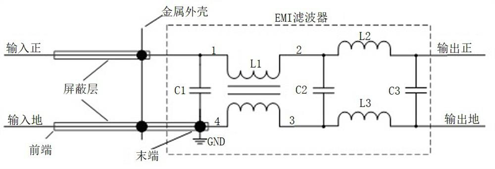
[0038] figure 1 It is a schematic diagram of the circuit principle of the EMI filter, and the parameter design and selection of each component are as follows.

[0039] The low-frequency ceramic capacitor C1 is a chip-type 0603 ceramic dielectric capacitor with a capacity of several uF, which is placed at the front end of the input to reduce the impedance of the input end and avoid abnormal power supply caused by input voltage resonance when connected to a linear stable impedance network (LSIN).

[0040] The high-frequency ceramic capacitor C2 is a chip type 0402 radio-frequency ceramic dielectric capacitor with a capacity of tens of pF and a high quality factor (Q value), especially requiring a low impedance between 100MHz and 1GHz, which is mainly driven by an external RS103 When the electric field common-mode interference coupling is introduced, the differential-mode current caused by the unequal impedance of the positive and negative lines to the ground provides a low-imped...


PUM


Abstract

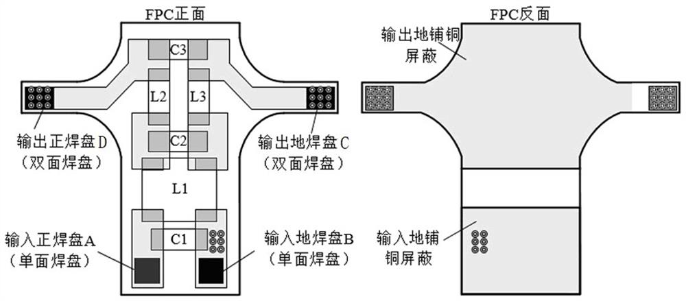
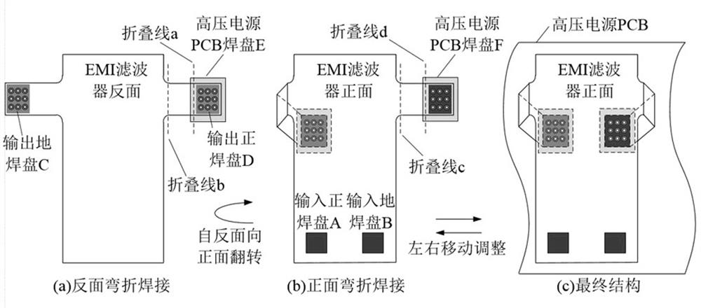
The invention belongs to the technical field of image intensifiers, and particularly provides an EMI filter for an image intensifier and an assembling method thereof, the EMI filter is of a two-stagecombined filtering structure, integrates a capacitor, an inductor and a magnetic bead component, adopts a flexible printed board to independently design a layout, and then welds the designed flexibleprinted board on a high-voltage power supply PCB in a laminated mode. The bonding pad on the front side is reinforced, the bonding pad on the back side is insulated, the bonding pad and the high-voltage power supply PCB are bent together, the bonding pad and the high-voltage power supply PCB are put into the metal shell, encapsulating by using silicone rubber to finish integral shaping, and finally welding the shielding wire and the metal shell by 360 degrees. Reasonable placement of the EMI filter is achieved, the problems that a small image intensifier cannot directly use the EMI filter or the placement position and layout design are not ideal are solved, meanwhile, the small image intensifier can be reliably assembled on the image intensifier, the electromagnetic compatibility of the image intensifier is effectively improved, and it is ensured that the image intensifier can meet the requirement of an electromagnetic compatibility test.

Description

technical field [0001] The invention belongs to the technical field of image intensifiers, and in particular relates to an EMI filter for image intensifiers and an assembly method thereof. Background technique [0002] The image intensifier is a vacuum electronic imaging device that enhances the image of the extremely weak light reflected by the target object through cathode photoelectric conversion, microchannel plate electron multiplication and phosphor screen electro-optic conversion. It is mainly composed of a vacuum image tube and a high-voltage power supply. The high-voltage power supply converts DC low voltage into high voltage to supply power to the image tube, and samples the fluorescent screen current to automatically adjust the amplitude and pulse width of the power supply voltage to ensure that the brightness of the image tube can be kept stable under low light and strong light conditions, realizing Automatic brightness control. [0003] The vacuum image tube is...

Claims


Application Information

Patent Timeline
Patent Type & Authority Applications(China)
IPC IPC(8): H03H7/01H05K1/18H05K3/34H05K3/36H05K5/06H05K9/00
CPCH03H7/0115H05K1/181H05K3/341H05K3/363H05K3/368H05K5/064H05K9/0064
Inventor 杜培德周盛涛朱文锦李亚情徐传平曾进能李晓露
Owner NORTH NIGHT VISION TECH
Learn More