Twisted-pair cage type hydrate continuous reaction device

A reaction device and hydrate technology, applied in gas fuel, petroleum industry, fuel and other directions, can solve the problems of insufficient conversion of micro droplets, increase the gas-liquid contact area, stuck stirring paddle, etc., to promote efficient and rapid generation. , The effect of increasing the gas-liquid contact area and increasing the degree of dispersion

Inactive Publication Date: 2020-12-25
QINGDAO UNIV OF SCI & TECH
View PDF7 Cites 3 Cited by
  • Summary
  • Abstract
  • Description
  • Claims
  • Application Information

AI Technical Summary

Problems solved by technology

The mechanical method can break through the limitation of the hydrate film preferentially formed at the gas-liquid interface, enhance mass transfer, increase the gas-liquid contact area, and achieve the purpose of promoting the rapid formation of hydrate. However, with the continuous generation of hydrates, defects such as impeller jamming and insufficient bubbling power make the promotion effect in the later stage more unsatisfactory, making the final hydrates mostly in the form of slurry or foam , the water conversion rate and gas storage rate are low. To achieve the ideal storage and transportation state, it is necessary to increase the post-compression granulation and other processing procedures
The spray method is to spray the liquid into the reactor in the form of micro-droplets to increase the gas-liquid contact area. However, since the micro-droplets quickly settle to the bottom of the reactor after being sprayed out, the micro-droplets are converted into hydrates. The process is short, resulting in insufficient droplet conversion

Method used


Image

  • Twisted-pair cage type hydrate continuous reaction device
  • Twisted-pair cage type hydrate continuous reaction device
  • Twisted-pair cage type hydrate continuous reaction device

Examples


Embodiment 1

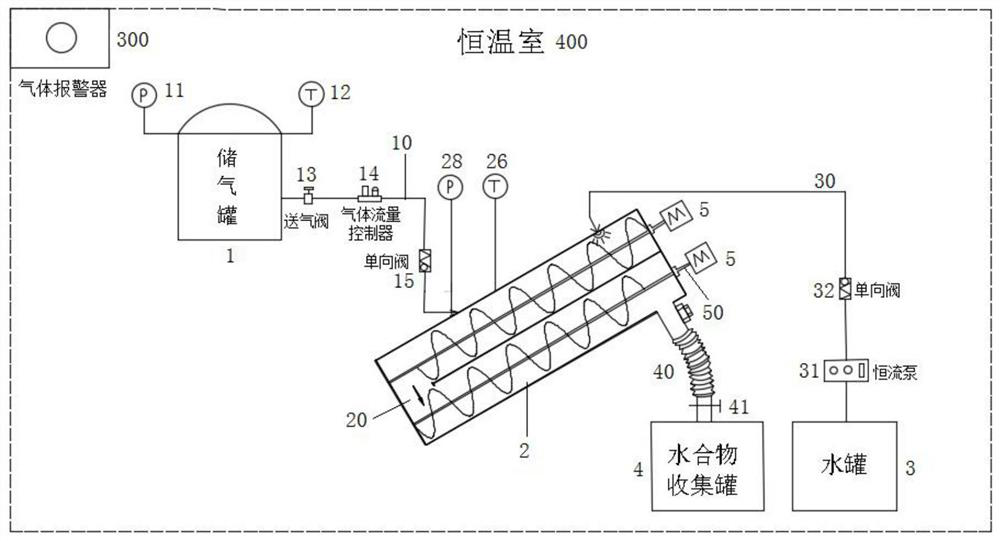
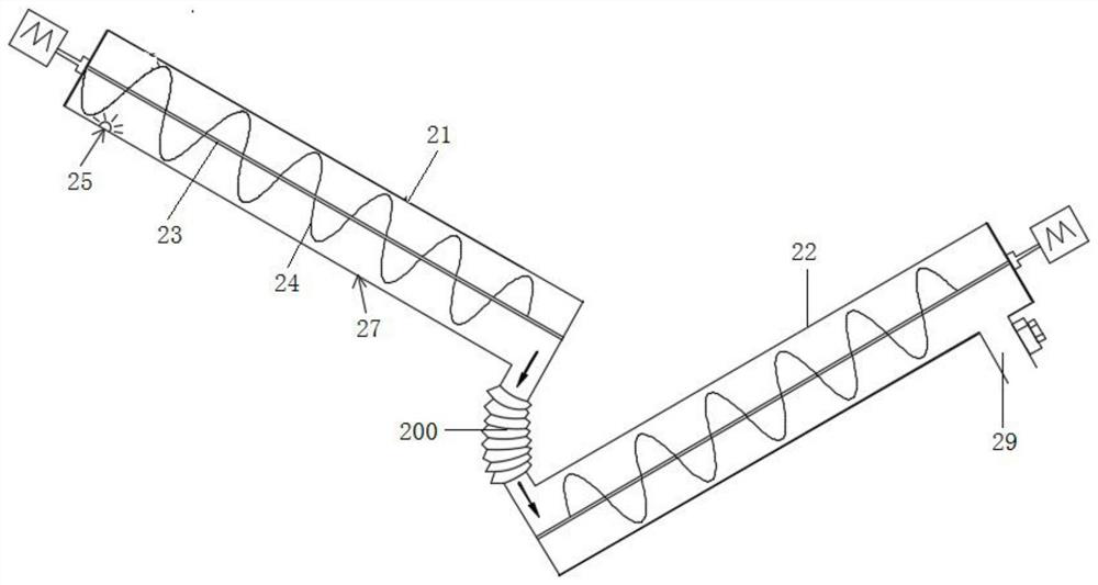
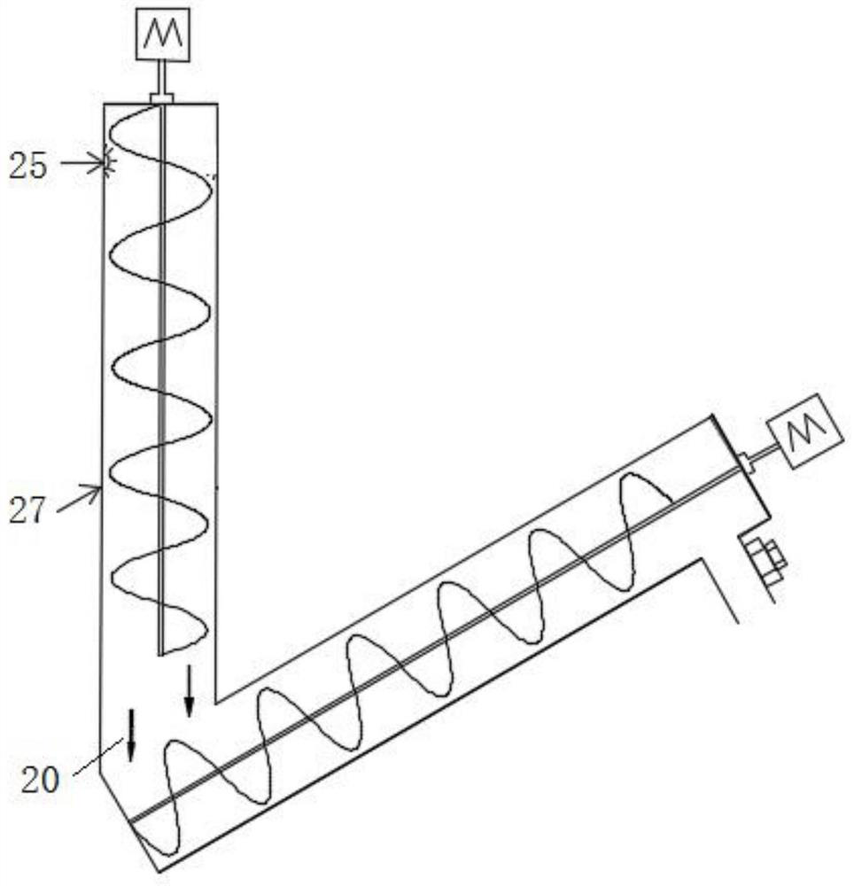
[0017]The main structure of the twisted cage type hydrate continuous reaction device involved in this embodiment includes a gas storage tank 1, a twisted cage reaction kettle 2, a water tank 3, a hydrate collection tank 4 and a motor 5; the gas storage tank 1 passes through the gas supply pipe The road 10 is connected with the twisted cage reactor 2, the gas storage tank 1 is provided with a No. 1 pressure sensor 11 and a No. 1 temperature sensor 12, and the gas supply pipeline 10 is provided with an air supply valve 13 and a gas flow controller in sequence along the flow direction of the medium. 14 and No. 1 one-way valve 15; the twisted cage reactor 2 is connected to the water tank 3 through the water supply pipeline 30, and the water supply pipeline 30 is provided with a constant flow pump 31 and a No. 2 one-way valve 32 in sequence along the flow direction of the medium; The twisted cage reactor 2 is flexibly connected to the hydrate collection tank 4 through the bellows 40...


PUM

PropertyMeasurementUnit
compressive strengthaaaaaaaaaa

Abstract

The invention belongs to the technical field of natural gas hydrate production and application, and relates to a twisted-pair cage type hydrate continuous reaction device, the main structure of whichcomprises a gas storage tank, a twisted-pair cage reaction kettle, a water tank, a hydrate collection tank and a motor; the gas storage tank is connected with the twisted-pair cage reaction kettle, and the twisted-pair cage reaction kettle is respectively connected with the water tank and the hydrate collection tank. The twisted-pair cage type reaction kettle is driven by a motor, and the fallingspeed of micro-droplets is reduced, the dispersion degree of the micro-droplets is increased, the gas-liquid contact area is increased, the conversion time of the micro-droplets is prolonged, and theconversion rate and the gas storage rate are increased by virtue of rotary stirring of stranding cage blades of the upper barrel body; secondary reinforced conversion and conveying are conducted on hydrate through spiral conveying of the stranding cage rods of the lower barrel body, the structural distribution and the connecting mode of the upper barrel body and the lower barrel body of the twisted-pair cage reaction kettle can be changed according to requirements, and when a hydrate channel which is in rigid connection is changed into a connecting channel of a flexible pipeline, The upper cylinder body and the lower cylinder body can change different inclination angles at the same time, and the optimal reaction effect is obtained.

Description

Technical field: [0001] The invention belongs to the technical field of production and application of natural gas hydrate, and in particular relates to a double-twisted cage type hydrate continuous reaction device, which realizes efficient, rapid and continuous reaction of natural gas hydrate. Background technique: [0002] As a high-quality, efficient and clean low-carbon energy source, natural gas can effectively reduce the emission of carbon, nitrogen, sulfur exhaust gas and solid particles by increasing its proportion in the primary energy consumption structure. With the continuous increase of environmental protection, natural gas consumption has maintained a rapid growth. However, at the present stage, in the industrial chain of natural gas supply, storage peak shaving, transportation and consumption, there are problems such as insufficient natural gas supply, single gas source supply structure, and lack of infrastructure for transmission-gas storage-peak shaving, which...

Claims


Application Information

Patent Timeline
Patent Type & Authority Applications(China)
IPC IPC(8): C10L3/08
CPCC10L3/08
Inventor 张国栋王飞
Owner QINGDAO UNIV OF SCI & TECH
Why Eureka
Try Eureka