Continuous production method for synthesizing hydrofluoroether

A production method and technology of hydrofluoroether, which is applied in the field of synthesizing hydrofluoroether, can solve the problems of long time-consuming synthesis process and high energy consumption, and achieve the effects of reducing equipment investment and floor space, increasing reaction speed, and increasing production capacity

Pending Publication Date: 2020-12-29
JUHUA GROUP TECH CENT
View PDF11 Cites 4 Cited by
  • Summary
  • Abstract
  • Description
  • Claims
  • Application Information

AI Technical Summary

Problems solved by technology

[0004] In order to solve the disadvantages of long time-consuming and high energy consumption in the synthesis process of the prior art, the present invention provides a continuous production method of hydrofluoroether, in which the raw materials are fed into the reactor, and the solid-liquid-vapor three-phase process is carried out while the materials are discharged. Separation; high reaction rate, low energy consumption, convenient discharge, and continuous production of hydrofluoroether products

Method used


Image

  • Continuous production method for synthesizing hydrofluoroether
  • Continuous production method for synthesizing hydrofluoroether
  • Continuous production method for synthesizing hydrofluoroether

Examples


Embodiment 1

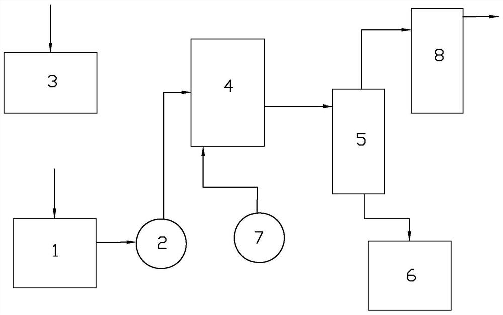
[0029] Alcohol and catalyst are prepared in proportion and loaded into the raw material tank (1) for subsequent use. Fluorine-containing olefins are fed into the fluorine-containing olefin buffer tank (3) for standby use. Then the alcohol, catalyst and fluorine-containing olefin are passed through the reaction tank (4) filled with the reaction solution of the flowmeter, the regulating valve and the first metering pump (2) according to the molar ratio of 1:0.1:1, and the residence time is controlled. In 4h, the reaction temperature was controlled at about 75°C, and then the reaction liquid was released from the bottom of the reaction kettle at the same time. The reaction solution enters the thin-film evaporator (5) for gas-liquid-solid three-phase separation. A cylinder is added inside the thin-film evaporator, wherein the upper part of the cylinder is a solid vertical cylinder, and the lower part is a metal sintered filterable inclined cylinder. The reaction liquid realizes I...

Embodiment 2

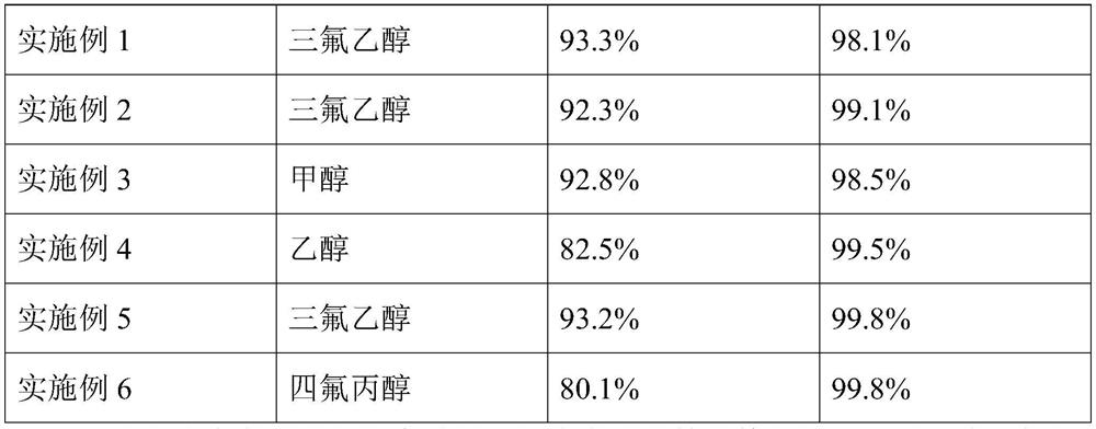
[0031] The basic steps are the same as in Example 1. The molar ratio of trifluoroethanol, potassium hydroxide, and tetrafluoroethylene is controlled to be 1:0.1:0.95, the residence time is controlled to be 1 h, and the temperature is controlled to be 50°C. After a continuous period of time, the reaction liquid was sampled and analyzed by chromatography, and the solvent peak was removed. The conversion rate of trifluoroethanol was 92.3%, and the selectivity was 99.1%.

Embodiment 3

[0033] The basic steps are the same as in Example 1, the molar ratio of methanol, potassium hydroxide and tetrafluoroethylene is controlled to be 1:0.1:1.1, the residence time is controlled to be 2h, and the temperature is controlled to be 100°C. After a continuous period of time, the reaction liquid was sampled and analyzed by chromatography, and the solvent peak was removed. The conversion rate of methanol was 92.8%, and the selectivity was 98.5%.


PUM


Abstract

The invention discloses a continuous process device and a continuous process method for synthesizing hydrofluoroether. The method is characterized by comprising the following steps: continuously introducing raw material alcohol in which a certain amount of catalyst is fused into a reaction kettle to react with tetrafluoroethylene, continuously discharging after a certain retention time, and separating through a film evaporator to obtain the hydrofluoroether; enabling a product and the raw material to enter a rectification system after becoming a gas phase, then recycling the raw material alcohol to a raw material tank, converting the waste catalyst into solid-phase salt to enter a waste catalyst tank, and recycling the remaining liquid-phase solvent back to the reaction kettle through a circulating pump for recycling. According to the method, a traditional batch reaction is changed into a continuous process, full-automatic control over the production process is achieved, meanwhile, thereaction rate is increased, the reaction condition is milder, the energy consumption cost is reduced, and the product stability is guaranteed.

Description

technical field [0001] The invention belongs to the field of chemical industry, and in particular relates to a continuous production method for synthesizing hydrofluoroethers. Background technique [0002] With the improvement of environmental protection requirements, the protection of the atmospheric ozone layer is increasingly strengthened, and the restriction and elimination of fluorine-containing refrigerants, foaming agents, and cleaning agents such as R22 are approaching. Hydrofluoroether has zero ozone depletion potential (ODP). With low warming potential (GWP) and short atmospheric residence time, it has little impact on the environment. It can be used in the fields of refrigerants, foaming agents, cleaning agents and heat transfer agents. It is an ideal substitute for a new generation of ODS (ozone depleting substances). [0003] At present, the production of hydrofluoroethers basically adopts a batch reaction process. First, 1:1 alcohol and solvent and 5% alkali me...

Claims


Application Information

Patent Timeline
Patent Type & Authority Applications(China)
IPC IPC(8): C07C41/06C07C43/12
CPCC07C41/06C07C43/12Y02P20/584
Inventor 徐锋沈凌云代现跃吴伟震姜澜姚晓艳宋小弦
Owner JUHUA GROUP TECH CENT
Why Eureka
Try Eureka