Doherty power amplifier based on dynamic power distribution

A technology of power amplifier and dynamic power, which is applied in the direction of improving amplifier efficiency, advanced technology, and climate sustainability. It can solve problems such as narrow bandwidth, narrow wavelength line bandwidth, and poor linearity, so as to increase bandwidth and reduce area. , Reduce the effect of passive loss and area

Active Publication Date: 2020-12-29
TSINGHUA UNIV
View PDF5 Cites 4 Cited by
  • Summary
  • Abstract
  • Description
  • Claims
  • Application Information

AI Technical Summary

Problems solved by technology

[0005] In view of this, the purpose of the present invention is to propose a Doherty power amplifier based on dynamic power distribution, to overcome problems such as poor linearity, narrow bandwidth, and large chip area in the existing Doherty amplifier technology
The present invention adopts a three-coil power combiner to realize the "load pull" effect between the main circuit amplifier and the auxiliary circuit amplifier, which is used to replace the quarter-wavelength line to undertake the role of load transformation, and solves the problem of the narrow bandwidth of the quarter-wavelength line At the same time, the present invention adopts a dynamic input power divider based on the change of input load impedance, so that the power distribution ratio of the main circuit and the auxiliary circuit changes with the change of the input signal, thereby improving the linearity of the overall circuit

Method used


Image

  • Doherty power amplifier based on dynamic power distribution
  • Doherty power amplifier based on dynamic power distribution

Examples


Embodiment Construction

[0017]In order to make the objectives, technical solutions, and features of the present invention clearer and clearer, specific implementations are described and described in detail below in conjunction with the accompanying drawings.

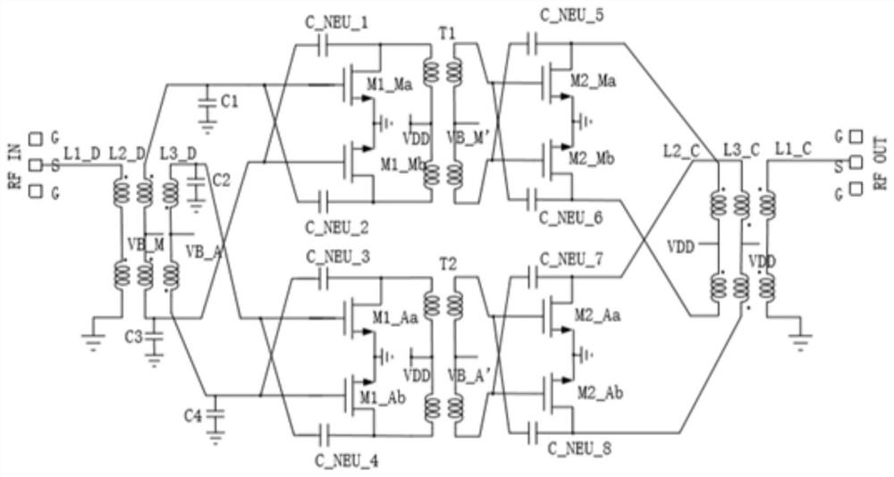
[0018]The present invention proposes a Doherty power amplifier based on dynamic power allocation, and its circuit structure is asfigure 1 As shown, it includes a dynamic power divider, two common source amplifiers and a power combiner connected in sequence; among them:

[0019]Two common source amplifiers, including two two-stage differential common source amplifiers, eight neutralizing capacitors, and two inter-stage matching transformers, which consist of eight transistors M1_Ma, M1_Mb, M1_Aa, M1_Ab, M2_Ma, M2_Mb, M2_Aa, M2_Ab, Two inter-stage matching transformers T1, T2 and eight neutralizing capacitors C_NEU_1, C_NEU_2, C_NEU_3, C_NEU_4, C_NEU_5, C_NEU_6, C_NEU_7, C_NEU_8 are composed of eight transistors M1_Ma, M1_Mb, M1_Aa, M1_Mb, M1_Aa, M1_M2, M2, ...


PUM


Abstract

The invention provides a Doherty power amplifier based on dynamic power distribution. The Doherty power amplifier comprises a dynamic power distributor, two common-source amplifiers and a power combiner which are connected in sequence, the two common-source amplifiers comprise two two-stage differential common-source amplifiers, eight neutralizing capacitors and two inter-stage matching transformers, the neutralizing capacitors are arranged at the differential input and output ends of the amplifiers in a crossed mode, and the inter-stage matching transformers are arranged between the first stage and the second stage of the main path amplifier and between the first stage and the second stage of the auxiliary path amplifier respectively; the dynamic power divider comprises three inductance coils and four capacitors, and the power combiner comprises three inductance coils. According to the dynamic power divider, through a load modulation effect, the power distribution ratio of a signal toa main circuit amplifier and an auxiliary circuit amplifier is changed when an input signal changes, so that the overall linearity of a circuit is improved; a three-coil coupled power combiner is used for replacing a traditional quarter-wavelength line structure, and the overall bandwidth of the circuit can be guaranteed while the load traction effect is generated.

Description

Technical field[0001]The invention relates to a Doherty power amplifier based on dynamic power allocation, and the field of analog integrated circuit design.Background technique[0002]In recent years, 5G technology has become a research hotspot. In the 5G communication system, one of the most critical components is the power amplifier (PA). Due to the high linearity requirements of the communication system, the power amplifier in the communication system often needs to work in the back-off zone. The millimeter-wave power amplifier with high power back-off efficiency is effective for effectively transmitting 5G modulated signals with a large peak-to-average power ratio. Important. Therefore, the linearity and efficiency of the power amplifier in the transceiver, especially the back-off efficiency, greatly limits the overall performance of the 5G communication system.[0003]Among various techniques for improving the back-off efficiency of power amplifiers, Doherty Power Amplifier (Doher...

Claims


Application Information

Patent Timeline
Patent Type & Authority Applications(China)
IPC IPC(8): H03F1/07
CPCH03F1/07Y02D30/70
Inventor 张雷吴沫君
Owner TSINGHUA UNIV
Why Eureka
Try Eureka