Biomass pyrolysis and gasification incinerator with differential rotating bed

A technology of pyrolysis gasification and rotating bed, which is applied in the field of energy science, can solve the problems of severe ash in the heating area of ​​the combustion chamber, low gasification efficiency, and high content of fly ash in flue gas, so as to improve energy conversion efficiency and heat energy utilization efficiency , The effect of low fly ash content in flue gas

Pending Publication Date: 2021-01-08
山东信科环境科学研究院有限公司
View PDF7 Cites 2 Cited by
  • Summary
  • Abstract
  • Description
  • Claims
  • Application Information

AI Technical Summary

Problems solved by technology

[0003] At present, the material layer of the existing pyrolysis gasification incinerator is directly stacked on the bottom slag discharge grate, there is no combustion space, and only a surface layer is formed on the surface to burn, so that the biomass is gasified in the pyrolysis gasification incinerator Incomplete combustion results in a great waste of energy. At the same time, due to the poor disturbance between the grate and the material layer, the grate is slagged; in addition, the commonly used pyrolysis gasification incinerator has a large air volume ratio, low gasification efficiency, and high combustion specificity. The content of fly ash in the flue gas is high, the heating area of ​​the combustion chamber is seriously ash, and the energy efficiency is low; the overall reaction stability is poor, and the utilization rate of heat energy is low, which makes it difficult to meet the heat load demand of users

Method used


Image

  • Biomass pyrolysis and gasification incinerator with differential rotating bed
  • Biomass pyrolysis and gasification incinerator with differential rotating bed
  • Biomass pyrolysis and gasification incinerator with differential rotating bed

Examples


Embodiment

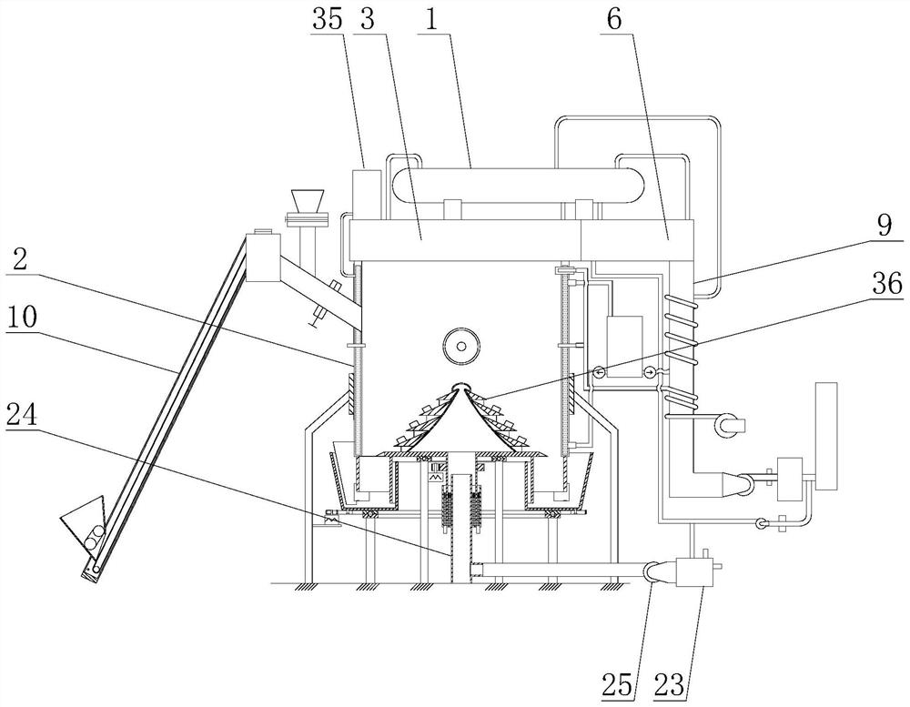
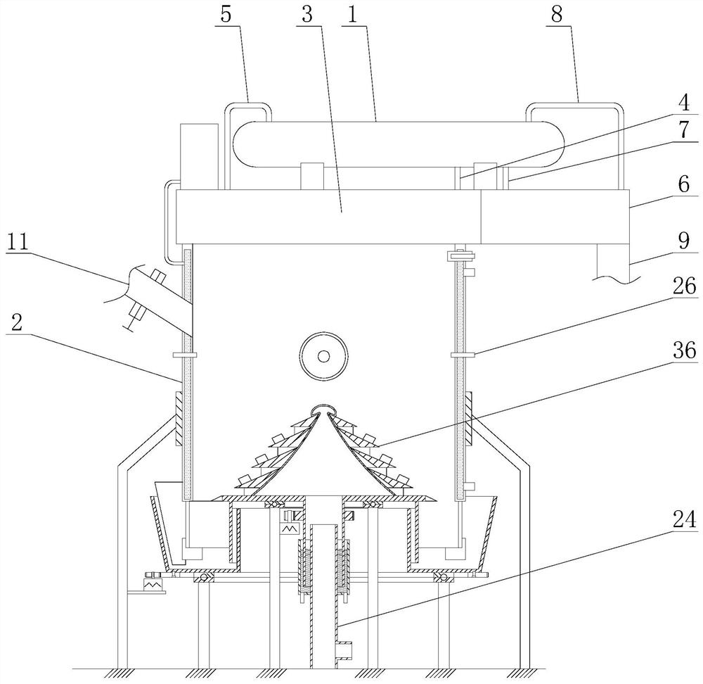
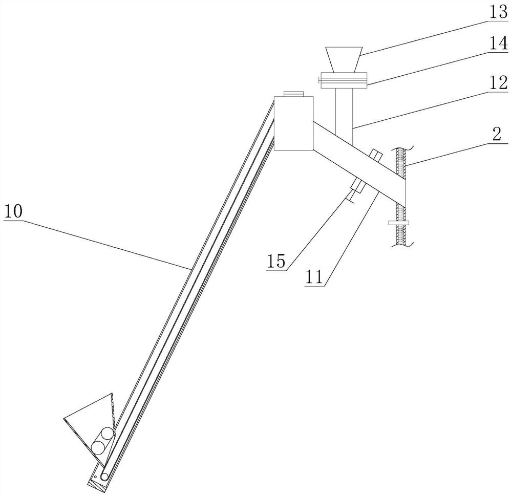
[0024] Example: as attached Figure 1-4 As shown, the present invention is a differential rotating bed biomass pyrolysis gasification incinerator, including a drum 1, a furnace body 2 with an open top, and the drum 1 is used for water storage. The top of the furnace body 2 is provided with a radiation heat exchanger 3 covering the top of the furnace body 2, and the radiation heat exchanger 3 covers the upper side of the furnace body 2, and the radiation heat exchanger 3 is used for direct heat exchange. The drum 1 is installed on the top of the radiation heat exchanger 3 , and a bracket is welded on the bottom of the drum 1 . The drum 1 is provided with a first water inlet pipe 4 and a first air outlet pipe 5 communicating with the radiation heat exchanger 3. The water in the drum 1 enters the radiation heat exchanger 3 through the first water inlet pipe 4 and is exchanged by radiation. After being heated by the heater 3, it becomes gas, which flows back into the drum 1 throu...


PUM


Abstract

The invention discloses a biomass pyrolysis and gasification incinerator with a differential rotating bed, and mainly relates to the technical field of energy science. The incinerator comprises a boiler barrel and a boiler body with an opening in the top, wherein a radiation heat exchanger covering the top end of the boiler body is arranged at the top of the boiler body, the boiler barrel is installed at the top of the radiation heat exchanger, a first flue communicating with the boiler body is arranged in the radiation heat exchanger, a convection heat exchanger is arranged on one side of theradiation heat exchanger, a second flue communicating with the first flue is arranged in the convection heat exchanger, an exhaust pipe communicating with the second flue is arranged at the end, awayfrom the radiation heat exchanger, of the convection heat exchanger, and a tower-shaped rotary air distribution disc and an air distribution disc driving device are arranged at the bottom in the furnace body. According to the incinerator, disturbing between a fire grate and a material layer can be increased, meanwhile, through proper air distribution, materials can be fully gasified, the heat exchange efficiency and the energy conversion efficiency can be improved, the service life is prolonged, the gasification strength is improved, the heat energy utilization rate can be increased, and theheat load requirements of users can be met.

Description

technical field [0001] The invention relates to the field of energy science and technology, in particular to a differential rotating bed biomass pyrolysis gasification incinerator. Background technique [0002] Pyrolysis gasification incinerator is a kind of environmental protection equipment that incinerates waste gas, waste liquid, solid waste fuel, domestic waste, animal carcasses, etc. A kind of product, divided into fixed incinerator and movable incinerator, there are many classification methods from different angles, according to furnace type classification can be divided into fixed grate furnace, mechanical grate furnace, fluidized bed incinerator (mainly used to deal with industrial waste), rotary kiln, etc. [0003] At present, the material layer of the existing pyrolysis gasification incinerator is directly stacked on the bottom slag discharge grate, there is no combustion space, and only a surface layer is formed on the surface to burn, so that the biomass is gas...

Claims


Application Information

Patent Timeline
Patent Type & Authority Applications(China)
IPC IPC(8): F23G5/027F23G5/46F23G5/44
CPCF23G5/027F23G5/46F23G5/444F23G2201/302F23G2201/303
Inventor 刘军刘恒明
Owner 山东信科环境科学研究院有限公司
Why Eureka
Try Eureka