

A niobium oxide gating tube
A niobium gate, magnesium oxide technology, applied in electrical components and other directions, can solve problems such as limited switching ratio, and achieve the effects of improving switching ratio, short production cycle, and stable process
- Summary
- Abstract
- Description
- Claims
- Application Information
AI Technical Summary
Problems solved by technology
Method used
Image

Examples
preparation example Construction
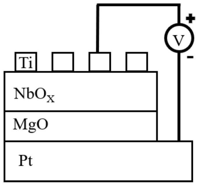
[0031] The structure of the niobium oxide gating tube added with magnesium oxide additional dielectric layer in the present invention is as follows from bottom to top: bottom electrode, lower additional dielectric layer, functional layer, and top electrode; its preparation method includes the following steps:
[0032] Step 1): For platinum bottom electrode (0.16μm 2 ~1mm 2 ) of the silicon substrate is pretreated;
[0033] Step 2): Install magnesium oxide targets, niobium oxide targets, and metal titanium targets on the magnetron sputtering equipment, and pass inert gas argon into the vacuum chamber of the equipment;
[0034] Step 3): Prepare an additional dielectric layer of magnesium oxide: turn on the magnetron sputtering RF power supply, and control the system pressure in the vacuum chamber to 2×10 -1 ~6×10 -1 Pa, the temperature is 290-330K, the power is 30-40W, the sputtering time is 20-30 seconds, after the deposition is completed, turn off the magnetron sputtering r...
Embodiment 1
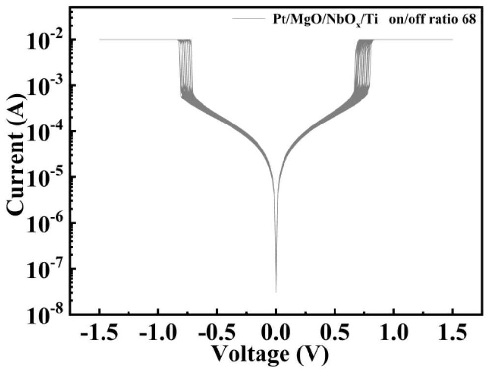
[0038]This embodiment is a niobium oxide gating tube added with an additional dielectric layer of magnesium oxide, and its structure from bottom to top is: bottom electrode, lower additional dielectric layer, functional layer, top electrode or bottom electrode, functional layer, and lower additional dielectric layer , a top electrode; preferably a bottom electrode, a lower additional dielectric layer, a functional layer, and a top electrode. In the niobium oxide gate tube with a preferred structure, the lower additional dielectric layer is deposited on the bottom electrode prior to the functional layer to ensure the uniformity of the dielectric layer, so as to play a better role. The gating ratio of the gating tube of this preferred structure can be increased to 68. Wherein the bottom electrode is a silicon dioxide substrate plated with metal platinum (gold, tungsten), the shape is rectangular, and the area is 0.64cm 2 ~1cm 2 ; The additional dielectric layer is a magnesium ...
Embodiment 2
[0059] This embodiment 2 is a niobium oxide gating tube with upper and lower magnesium oxide additional dielectric layers, its gating ratio can reach 161, and its structure from bottom to top is: bottom electrode, lower additional dielectric layer, functional layer, upper additional Dielectric layer, top electrode. Wherein the bottom electrode is a silicon dioxide substrate plated with metal platinum (gold, tungsten), the shape is rectangular, and the area is 0.64cm 2 ~1cm 2 ; The lower additional dielectric layer is a magnesium oxide film with a thickness of 1-5nm and a rectangular shape, but its size is slightly smaller than that of the bottom electrode, which is used to reserve the bottom electrode, with an area of 0.48cm 2 ~0.8cm 2 The functional layer is a niobium oxide thin film with a thickness of 80-200nm and a rectangular shape with the same area as the lower additional dielectric layer; the upper additional dielectric layer is a magnesium oxide thin film with a t...
PUM
| Property | Measurement | Unit |
|---|---|---|
| thickness | aaaaa | aaaaa |
| thickness | aaaaa | aaaaa |
| thickness | aaaaa | aaaaa |
Abstract
Description
Claims
Application Information