Broadband terahertz mixer with low frequency conversion loss

A frequency conversion loss and terahertz technology, applied in the field of solid-state terahertz devices, can solve the problems of complex RF and local oscillator matching circuits, increase or decrease of circuit size, increase of circuit loss, etc., to improve operating frequency and stability, and reduce transmission loss , The effect of simplifying the circuit size

Active Publication Date: 2021-02-05
10TH RES INST OF CETC
View PDF9 Cites 6 Cited by
  • Summary
  • Abstract
  • Description
  • Claims
  • Application Information

AI Technical Summary

Problems solved by technology

[0003] The defects and shortcomings of the prior art terahertz subharmonic mixers are: in the traditional terahertz mixer design, the radio frequency signal is loaded on the antiparallel diode, and the radio frequency ground loop design almost adopts four The one-wavelength line is grounded; the operating frequency of the mixer is low and the bandwidth is narrow
Usually, manual assembly of Schottky diodes will inevitably have assembly errors, as well as the introduction of parasitic capacitance and inductance, so there will be problems of frequency offset and low operating frequency
Since the anti-parallel diode relies on a quarter-wavelength line for RF grounding, its bandwidth has certain narrow-band characteristics; the structure of the mixer is complex, and the frequency conversion loss is large
The traditional terahertz mixer design often separates the local oscillator RF probe and matching, which easily causes the final mixer structure to be too long
On the one hand, if the quartz substrate is too long, the quartz substrate will be more likely to be broken, which will increase the difficulty of processing and assembling the substrate; on the other hand, it will increase the transmission loss of the terahertz signal
In order to obtain greater bandwidth gains, RF and local oscillator matching circuits are often more complex and bloated
An overly complex matching circuit will not only increase or decrease the size of the circuit, but also increase the loss of the circuit, resulting in greater frequency conversion loss

Method used


Image

  • Broadband terahertz mixer with low frequency conversion loss

Examples


Embodiment Construction

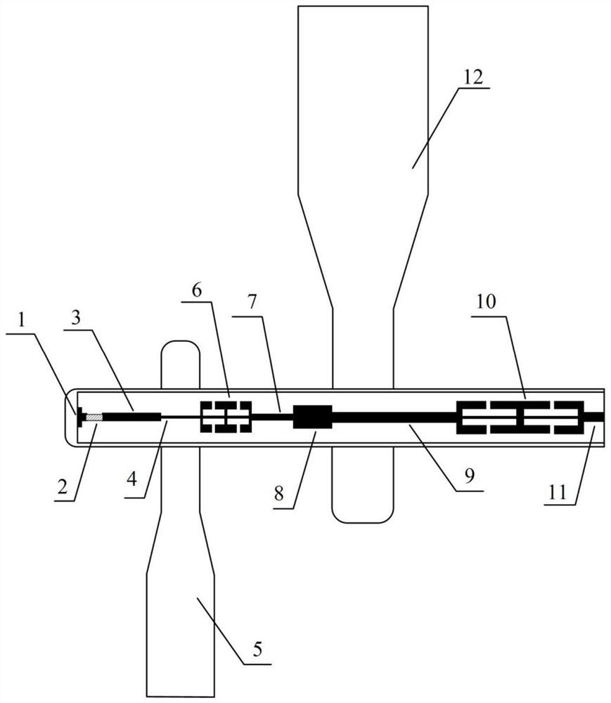
[0013] refer to figure 1 . In the preferred embodiment described below, a broadband low conversion loss terahertz mixer includes: a radio frequency height reduction waveguide, a local vibration height reduction waveguide, a quartz circuit cavity and a quartz circuit, and the bottom of the quartz substrate is coated with silver paste Connecting the quartz circuit cavity is characterized in that: the quartz circuit cavity runs through the radio frequency height reduction waveguide and the local vibration height reduction waveguide, and the antiparallel terahertz Schottky diode 2 is placed on the radio frequency DC ground microstrip line 1 on the upper surface of the quartz substrate Between the RF matching stub 3 and the radio frequency transition suspension microstrip line 4 in sequence, the local oscillator low-pass filter 6, the local oscillator matching stub 7 and the local oscillator matching stub 8 are connected in series, and the local oscillator transition microstrip 9 r...


PUM


Abstract

The invention discloses a broadband terahertz mixer with low frequency conversion loss, and aims to achieve high isolation, simple structure, high working frequency, low frequency conversion loss andwide working bandwidth. According to the technical scheme, a quartz circuit cavity penetrates through a radio frequency height reduction waveguide and a local oscillation height reduction waveguide, an anti-parallel terahertz Schottky diode is arranged between a radio frequency direct current ground microstrip line and a radio frequency matching branch knot on the upper surface of a quartz substrate, and the radio frequency direct current ground microstrip line and the radio frequency matching branch knot sequentially pass through a radio frequency transition suspension microstrip line; a local oscillator low-pass filter and a local oscillator matching network are connected in series, the local oscillator transition microstrip penetrates through the local oscillator height reduction waveguide and is connected with the intermediate frequency low-pass filter in series, and finally a frequency mixing signal is output through an intermediate frequency port.

Description

technical field [0001] The invention relates to a solid-state terahertz device applied in the technical field of terahertz, more specifically, to a wide-band low-frequency conversion loss terahertz mixer. Background technique [0002] With the development of terahertz technology, terahertz solid-state devices have shown unprecedented application potential in radio astronomy, nondestructive testing, object imaging, security inspection, high-speed communication and other fields. For a superheterodyne receiver in the terahertz frequency band, the mixer is an essential key component of the receiving front end, which can realize the function of spectrum shifting. However, due to the lack of mature terahertz low-noise amplifier chips, the first stage of the terahertz receiving front end is usually a terahertz mixer. Therefore, the specifications of the mixer greatly affect the overall performance of the receiving system. For example, the size of the frequency conversion loss of t...

Claims


Application Information

Patent Timeline
Patent Type & Authority Applications(China)
IPC IPC(8): H03D7/16
CPCH03D7/16
Inventor 熊阳裴乃昌何毅龙李凯
Owner 10TH RES INST OF CETC
Why Eureka
Try Eureka