Boiler flue gas waste heat recycling system

A waste heat recovery and boiler flue gas technology, applied in the heating system, application, heating method, etc., can solve the problems of low efficiency, cumbersome operation, no removal of harmful substances, etc., and achieve the effect of convenient use and simple operation

Inactive Publication Date: 2021-02-19
SHANDONG DAIRONG ENERGY SAVING ENVIRONMENTAL PROTECTION TECH
View PDF3 Cites 1 Cited by
  • Summary
  • Abstract
  • Description
  • Claims
  • Application Information

AI Technical Summary

Problems solved by technology

[0003] In the existing technology, the waste heat recovery and utilization device of recovery boiler flue gas has a complex structure. When purifying flue gas to fix particles, the waste water is directly discharged, which cannot achieve the recovery effect, and the waste water discharged at high temperature will pollute the environment and cannot be reused. , through the direct discharge of ordinary purified gas, it cannot be used and cannot be truly pollution-free. Instead, it causes pollution to the atmospheric environment. The filtered gas and liquid harmful substances are not removed and cannot be effectively used. Causes multiple pollutions, the high-temperature waste heat formed by liquid and flue gas cannot be completely cooled, the efficiency is relatively low, the purification is not thorough, and the operation is cumbersome, time-consuming and labor-intensive

Method used


Image

  • Boiler flue gas waste heat recycling system
  • Boiler flue gas waste heat recycling system
  • Boiler flue gas waste heat recycling system

Examples


Embodiment Construction

[0021] The following will clearly and completely describe the technical solutions in the embodiments of the present invention with reference to the accompanying drawings in the embodiments of the present invention. Obviously, the described embodiments are only some, not all, embodiments of the present invention. Based on the embodiments of the present invention, all other embodiments obtained by persons of ordinary skill in the art without making creative efforts belong to the protection scope of the present invention.

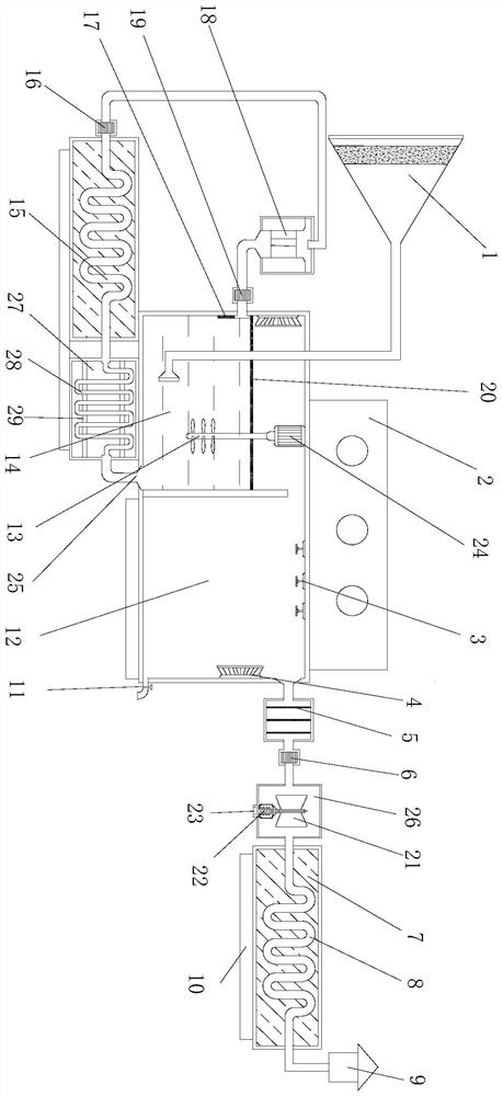
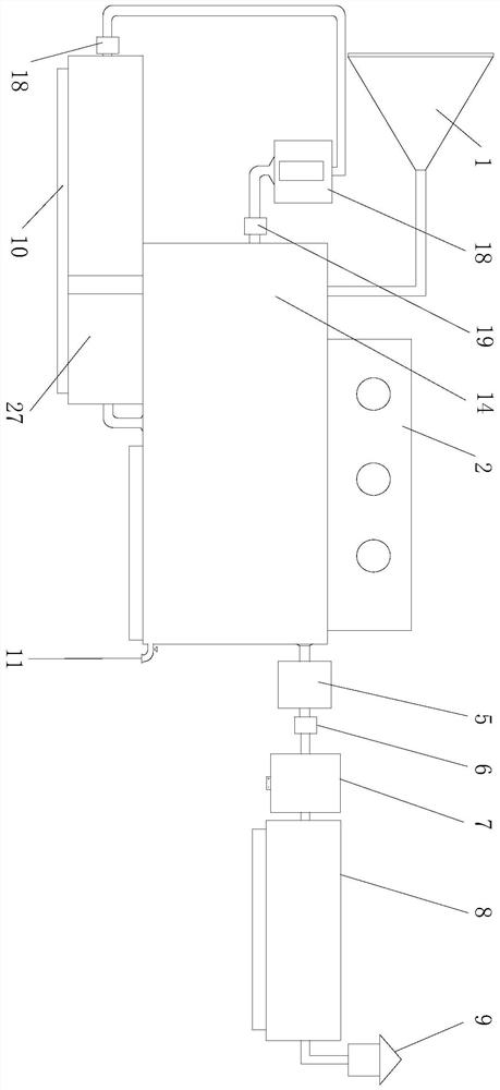
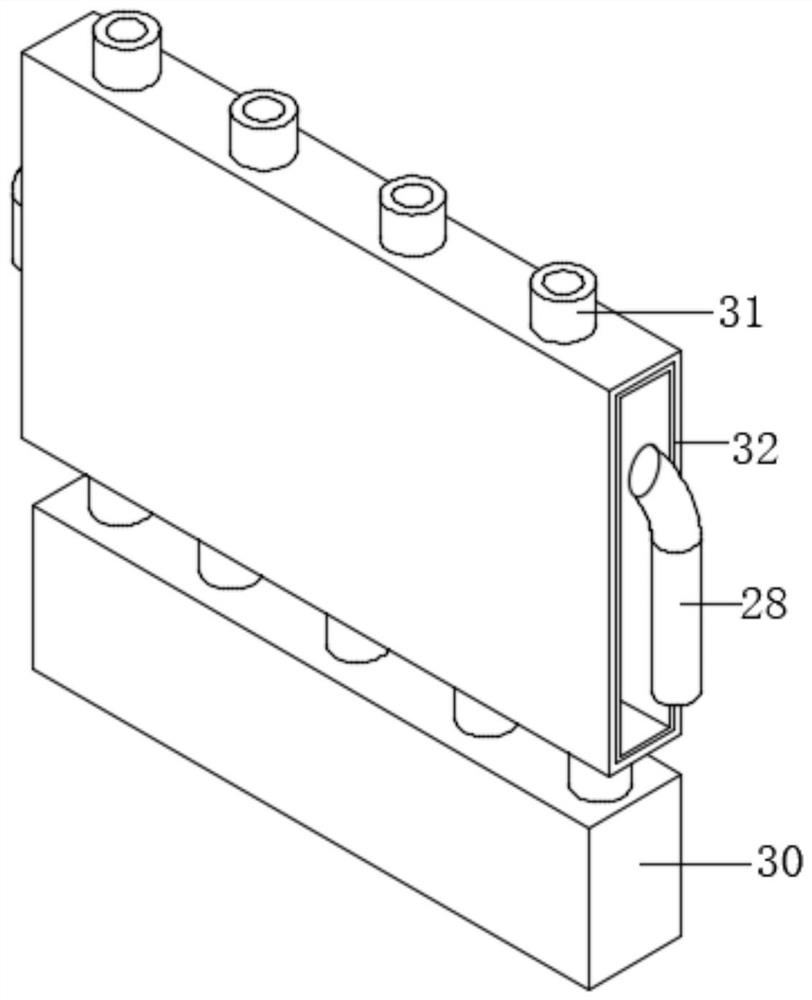
[0022] see Figure 1~3 , in an embodiment of the present invention, a boiler flue gas waste heat recovery and utilization system includes a flue gas inlet pipe 1, an activated carbon primary filter layer is arranged in the flue gas inlet pipe 1, and the output end of the flue gas inlet pipe 1 is arranged in a reaction pool 14, and the reaction A suspension frame 2 is fixed above the pool 14, and the suspension frame 2 plays a supporting role, so that the heat ...


PUM


Abstract

The invention discloses a boiler flue gas waste heat recycling system, and relates to the field of flue gas purification devices. The system comprises a flue gas inlet pipeline, an activated carbon primary filter layer is arranged in the flue gas inlet pipeline, the output end of the flue gas inlet pipeline is arranged in a reaction tank, a suspension bracket is fixed above the reaction tank, a motor is fixed above the inside of the reaction tank through bolts, and a stirrer fixed below the motor, a fan is fixed above the left side of the reaction tank through bolts; a liquid inlet pipeline isarranged below the fan; a water level sensor is fixed below the fan; the left side of the liquid inlet pipeline is fixedly connected with a water pump; the water pump is connected with a water levelobservation chamber through a pipeline; the water level observation chamber is connected with a lower pressure increasing valve through a left side pipeline, the right side of the pressure increasingvalve is connected with a liquid condensing pipe; the right side of the liquid condensing pipe is connected with a heating box through a pipeline; the right side of the heating box is connected to a water outlet, a gas reaction chamber is arranged on the right side in the reaction tank, and a spraying head is fixed to the top of the gas reaction chamber. The device can purify flue gas waste heat in a filtering and condensing manner so that liquid and gas are recycled, and the purification efficiency is improved.

Description

technical field [0001] The invention relates to the field of flue gas purification devices, in particular to a boiler flue gas waste heat recovery and utilization system. Background technique [0002] Boiler flue gas waste heat recovery and utilization device is a boiler flue gas waste heat recovery and utilization system designed for high-temperature flue gas of industrial waste gas. The purification system is widely used in glass, metallurgy, smelting, petrochemical, building materials, ceramics, textile and other industries with waste heat recovery of flue gas (or other high-temperature polluting gases) above 280 °C. That is, as long as the exhaust gas temperature is higher than 280 ℃, industrial boilers, fluidized bed boilers, heat transfer oil furnaces, smelting furnaces, metallurgical furnaces, blast furnace hot blast stoves, heating furnaces, as well as chemical fertilizer plants and paper mills can be applied. [0003] In the existing technology, the waste heat reco...

Claims


Application Information

Patent Timeline
Patent Type & Authority Applications(China)
IPC IPC(8): B01D50/00B01D53/40B01D53/79B01D53/04B01D53/00F23J15/02F23J15/06F24D15/00F01K27/00F01D15/10
CPCB01D53/40B01D53/79B01D53/0407B01D53/002F23J15/025F23J15/06F24D15/00F01K27/00F01D15/10B01D2253/102B01D2258/0283B01D50/60Y02E20/30
Inventor 李延平李燕春李燕宾翟现刚黄振波束海涛许庆涛
Owner SHANDONG DAIRONG ENERGY SAVING ENVIRONMENTAL PROTECTION TECH
Why Eureka
Try Eureka