
A system and method for mixing and burning sludge in a medium-temperature separation circulating fluidized bed boiler

A circulating fluidized bed and sludge technology, which is applied in the direction of fluidized bed combustion equipment, combustion methods, fuel burned in a molten state, etc., can solve the problems of uneven distribution of sludge, immaturity, and high moisture content, and achieve the goal of conveying Simple and reliable, prevent excessive agglomeration, continuous delivery effect

Active Publication Date: 2022-08-02
XIAN THERMAL POWER RES INST CO LTD
View PDF8 Cites 0 Cited by
  • Summary
  • Abstract
  • Description
  • Claims
  • Application Information

AI Technical Summary

Problems solved by technology

[0006] 1) High moisture content, usually up to 80%;
[0007] 2) High content of microorganisms and pathogens;
[0008] 3) The stench pollutes the environment;
The system layout of the central feeding scheme is more affected by site conditions, and the layout is difficult; the feeding point is generally located in the middle of the side wall, and the ratio of width to depth of the circulating fluidized bed boiler furnace is very different. If the material is fed on the side wall, it will inevitably cause sludge The distribution is severely uneven, which affects the stability of the boiler operation; in addition, the mechanical failure of the spray gun in the middle feeding mode is relatively high, and the later maintenance workload is large
At the same time, the moisture content of the sludge is 80%, which is much higher than the moisture content of the coal slime, which is 30%. The feed material in the middle of the furnace is close to the bed, which will greatly affect the stability of the bed temperature.
To sum up, for co-firing sludge, the feed material in the middle of the furnace is still not mature enough for medium-temperature separation circulating fluidized bed boilers.

Method used


Image

  • A system and method for mixing and burning sludge in a medium-temperature separation circulating fluidized bed boiler

Examples


Embodiment Construction

[0031] The present invention will be further described in detail below with reference to the accompanying drawings.

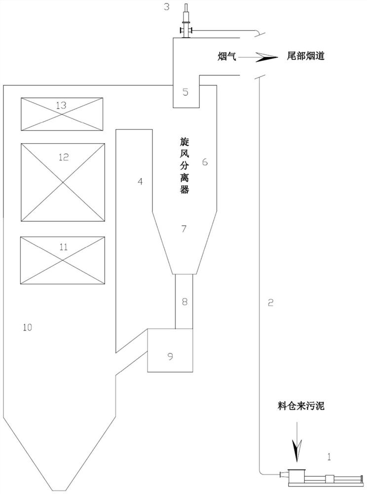
[0032] see figure 1 , The present invention provides a system for mixing and burning sludge in a medium-temperature separation circulating fluidized bed boiler, the system includes a plunger pump 1, a pumping pipeline 2, a vertical feeder 3, a medium-temperature separation cyclone 4, a return Feeding device 9, circulating fluidized bed boiler furnace 10. The medium-temperature separation cyclone 4 consists of a central barrel 5, a separator barrel 6, a separator cone 7 and a separator ash discharge port 8, the circulating fluidized bed boiler is a medium-temperature separation circulating bed boiler, and the circulating fluidized bed boiler furnace 10 An evaporator 11 , a superheater 12 and a high temperature economizer 13 are arranged in the upper part in order from bottom to top. The sludge from the silo is inhaled from the inlet of the plunger pump 2, and ...


PUM


Abstract

The invention discloses a system and method for mixing and burning sludge in a medium-temperature separation circulating fluidized bed boiler. The system includes a medium-temperature separation cyclone separator and the like. The sludge is transported through the pumping pipeline by the plunger pump to the vertical feeder set above the flue at the corner of the central cylinder of the medium-temperature separation cyclone. The vertical feeder cuts and disperses the agglomerated sludge and enters the center The sludge passes through the central cylinder, cylinder body and cone from top to bottom. During the movement, it directly contacts the rising medium-temperature flue gas for heat exchange. Under the action of turbulent flow, the water in the sludge evaporates rapidly, and the particles shrink and collapse. , Redispersed, the moisture content of the sludge drops to about 40% and then falls into the ash discharge port, mixed with the circulating ash, and then transported to the furnace of the circulating fluidized bed boiler through the return device for combustion. The invention reduces the moisture content of the sludge through the medium temperature separation cyclone separator, and realizes the purpose of mixing and burning the sludge on the medium temperature separation fluidized bed boiler.

Description

technical field [0001] The invention belongs to the technical field of coal-fired coupled sludge power generation, and in particular relates to a system and method for mixing sludge with a medium-temperature separation circulating fluidized bed boiler. Background technique [0002] With the rapid improvement of my country's urbanization rate and level of urbanization, my country's urban sewage treatment capacity has been continuously improved. By the end of 2016, the total amount of wastewater discharged nationwide was 71.11 billion tons, and domestic sewage discharge accounted for 71.4%. Only 31 major cities and towns had domestic sewage discharge of 17.681 billion. The urban domestic sewage treatment rate is 93.44%, and the sludge output of major cities in the country is about 40 million tons based on 80% moisture. Although municipal sludge is rich in organic matter and various nutrients, it also contains a large number of pathogenic bacteria, parasite eggs, heavy metals,...

Claims


Application Information

Patent Timeline
Patent Type & Authority Patents(China)
IPC IPC(8): F23G5/30F23G5/44F23G5/46F23C10/10F23C10/26
CPCF23G5/30F23G5/444F23G5/44F23G5/46F23C10/10F23C10/26
Inventor 王慧青赵永坚冯斌查琼亮赵帅
Owner XIAN THERMAL POWER RES INST CO LTD
Learn More