Hybrid magnetic circuit permanent magnet synchronous motor for electric automobile and driving method thereof

A permanent magnet synchronous motor and hybrid magnetic circuit technology, applied in electric vehicles, motor generator control, magnetic circuit rotating parts, etc., can solve problems such as large harmonics, large leakage flux, and prominent cogging torque problems. , to achieve the effect of good structure compactness, good heat dissipation, and high effective magnetic density of the air gap

Active Publication Date: 2021-02-23
SHANDONG UNIV
View PDF9 Cites 0 Cited by
  • Summary
  • Abstract
  • Description
  • Claims
  • Application Information

AI Technical Summary

Problems solved by technology

[0007] 3. In the rotor structure of the existing built-in permanent magnet synchronous motor, the permanent magnets of the rotor are arranged and combined to realize the "magnetism gathering effect", so the magnetic poles of the rotor core have a high magnetic density and a large leakage flux
The rotor leakage flux passes through the end of the motor rotor or the end cover is closed, and because the total magnetic flux generated by the permanent magnet is constant, the existence of the end leakage flux not only makes the magnetic field distribution at the two ends of the motor uneven, but also reduces the Effective flux utilization, which reduces the power density and torque density of the motor
In order to overcome the influence of the leakage flux at the end, in the actual design, the motor rotor often adopts an overhang structure. This structure makes the axial length of the rotor core larger than the axial length of the motor stator core, but this structure significantly increases the axial length of the motor. This further increases the amount of iron core material and manufacturing cost of the motor, and the structure essentially does not play a role in suppressing the leakage flux at the end
[0008] 4. According to the different paths of the d-axis flux during the field-weakening operation of the motor, the rotor structure of the existing built-in permanent magnet motor can be divided into two types: the first type, when the field-weakening control is performed, the d-axis generated by the armature winding The magnetic flux will directly pass through the permanent magnet of the motor, so this structure often causes irreversible demagnetization of the permanent magnet; the second type, when performing field weakening control, the d-axis magnetic flux generated by the armature winding does not directly pass through the permanent magnet, but The excitation magnetic field generated by the d-axis current forces more rotor flux to pass through the end of the motor and the end cover to close. This structure significantly increases the leakage flux of the motor, and the reluctance at the end of the motor is usually larger than that of the air gap. Much more, so the d-axis current required for field weakening is larger, significantly increasing the cost of the motor power inverter and the copper loss of the winding
[0009] 5. The armature back electromotive force harmonic of the existing permanent magnet synchronous motor is relatively large, and the cogging torque problem is prominent, so it often brings serious vibration and noise problems
At present, the method of stator inclined slot or rotor inclined pole is usually used to improve the counter electromotive force harmonic and weaken the cogging torque, but the processing technology of stator inclined slot and rotor inclined pole is more complicated, which greatly increases the manufacturing cost, and will be reduced to a certain extent The average electromagnetic torque of the motor, reducing the torque density and power density of the motor

Method used


Image

  • Hybrid magnetic circuit permanent magnet synchronous motor for electric automobile and driving method thereof
  • Hybrid magnetic circuit permanent magnet synchronous motor for electric automobile and driving method thereof
  • Hybrid magnetic circuit permanent magnet synchronous motor for electric automobile and driving method thereof

Examples


Embodiment

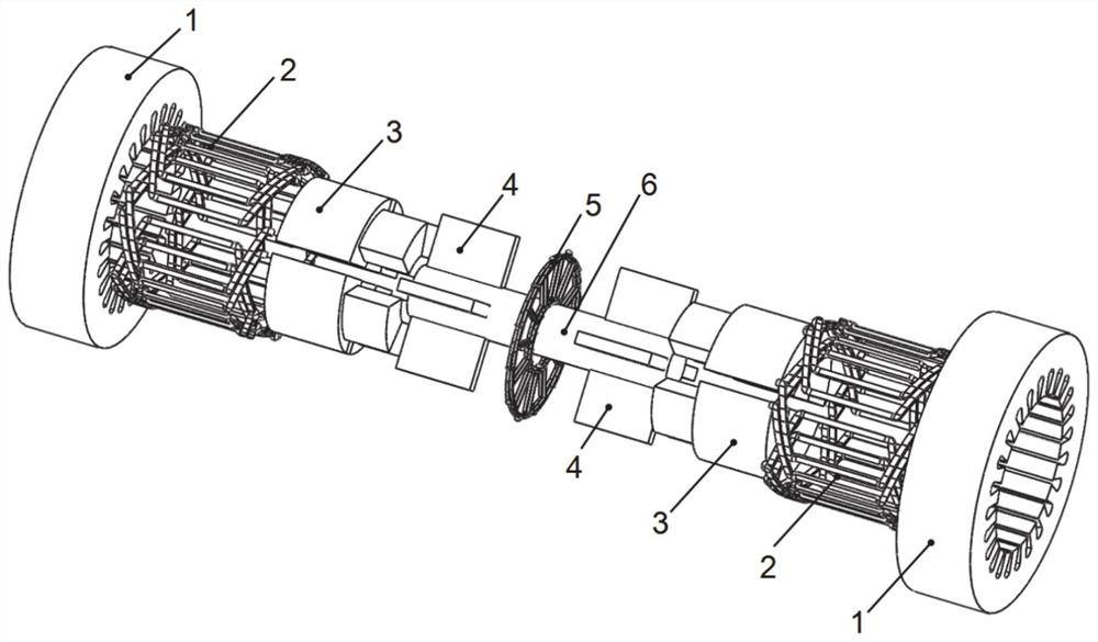
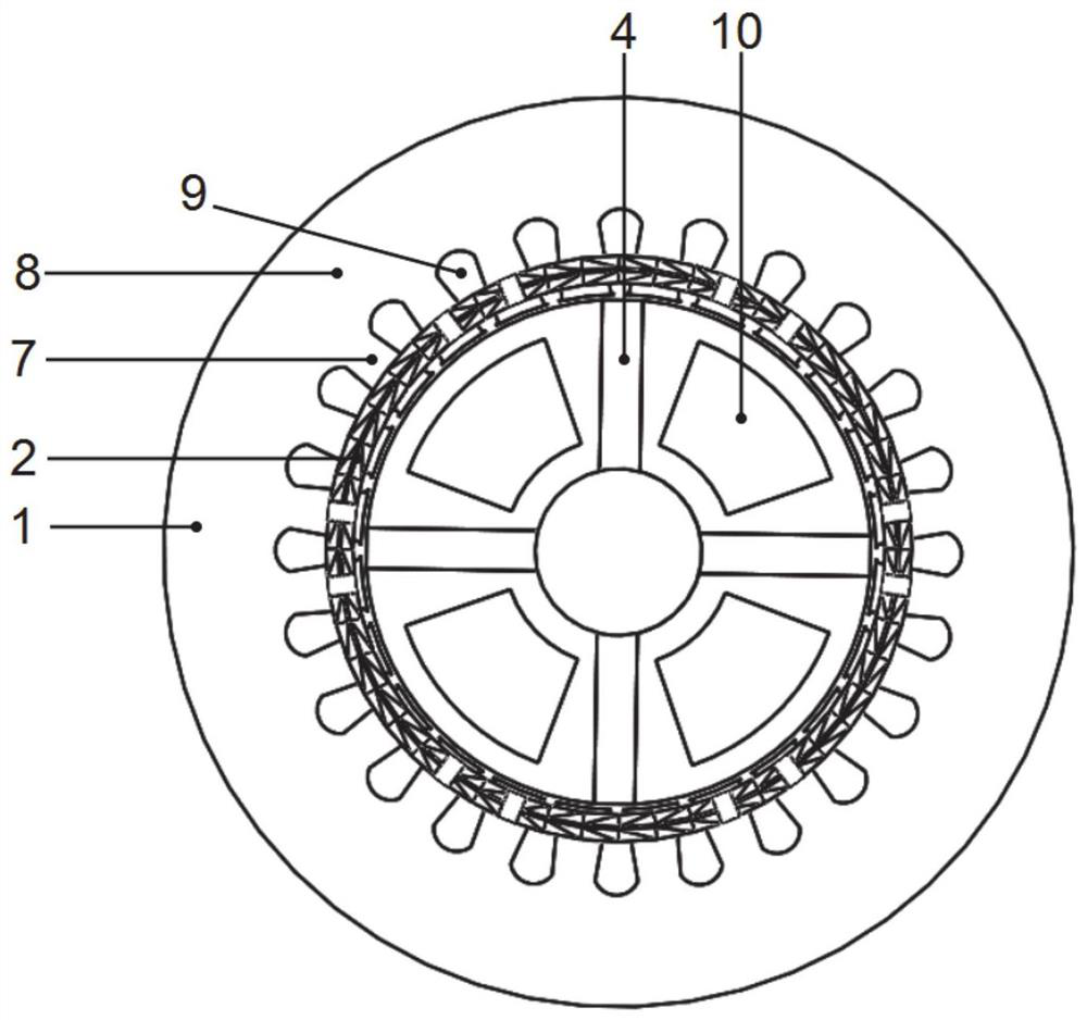
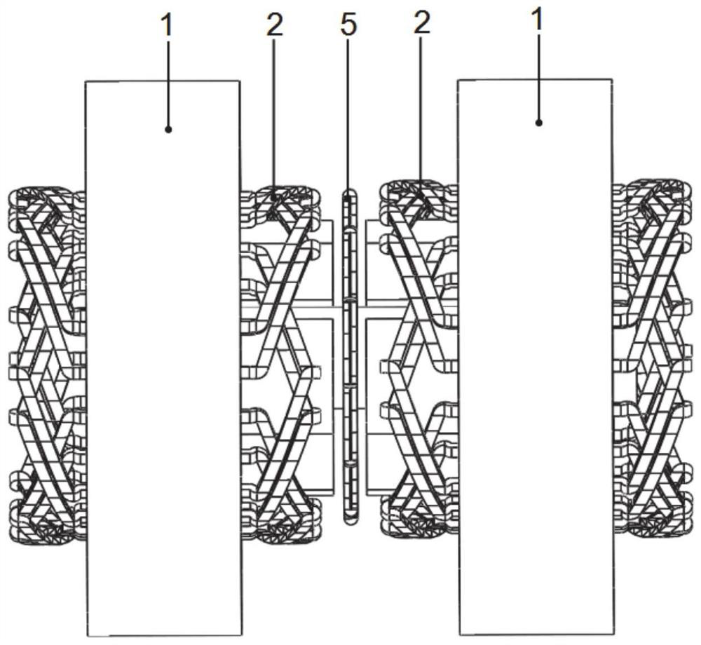
[0068] like figure 1 As shown, the overall three-dimensional schematic diagram of the motor, the number of phases of the motor in this embodiment is 3, the number of radial stator teeth is 24, the number of rotor slots is 8, the number of permanent magnet blocks is 8, the number of radial magnetic poles is 4, and the number of axial magnetic poles is 4. This embodiment includes a radial stator, an axial winding and a rotor. The radial stator is made of laminated silicon steel sheets, such as figure 2 As shown, the radial stator includes radial stator teeth 7, radial stator yoke 8 and radial stator slots 9, radial armature windings 2 are placed in the radial stator slots 9, and the radial armature windings 2 can be distributed windings , concentrated winding or stacked winding, the number of poles of the radial armature winding is consistent with the number of radial magnetic poles of the rotor, the radial stator and the rotor are coaxial, and there is a radial air gap between...


PUM


Abstract

The invention provides a hybrid magnetic circuit permanent magnet synchronous motor for an electric automobile and a driving method of the hybrid magnetic circuit permanent magnet synchronous motor. The hybrid magnetic circuit permanent magnet synchronous motor comprises radial stators, an axial winding, radial windings and solid rotors, and the two sections of coaxially connected rotors are arranged in the two radial stators and are coaxially arranged with the radial stators; the axial winding is concentrically placed in the middle of the two sections of rotors and equally divides the rotorsinto two parts in the axial direction, permanent magnets are placed in the rotors to generate radial magnetic poles and axial magnetic poles, and one part of magnetic flux generated by the permanent magnets enters the radial stators through the radial magnetic poles and then is interlinked with a radial armature winding to form radial main magnetic flux; the other part is linked with an axial armature winding through the axial magnetic poles to form axial main magnetic flux and finally returns to the permanent magnet of the rotor on the other side, and the radial main magnetic flux is connected with the axial main magnetic flux in parallel; according to the invention, the magnetic flux leakage effect of the end part of the motor is weakened, the material utilization rate is improved, the power density is improved, the magnetism-increasing operation and the flux-weakening speed-expanding operation can be flexibly realized, and the economic operation range of the motor is broadened.

Description

technical field [0001] The disclosure belongs to the technical field of permanent magnet synchronous motors, in particular to a hybrid magnetic circuit permanent magnet synchronous motor for electric vehicles and a driving method thereof. Background technique [0002] The statements in this section merely provide background information related to the present disclosure and do not necessarily constitute prior art. [0003] Permanent magnet motors are usually divided into four categories: permanent magnet DC motors, asynchronous start permanent magnet synchronous motors, permanent magnet brushless DC motors and speed-adjustable permanent magnet synchronous motors. The structural difference between the permanent magnet DC motor and the ordinary DC motor is that the former cancels the excitation winding and the pole core, and replaces it with a permanent magnet pole. It has the characteristics of simple structure, high reliability, high efficiency, small size and light weight. ...

Claims


Application Information

Patent Timeline
Patent Type & Authority Applications(China)
IPC IPC(8): H02K16/00H02K1/16H02K3/28H02K1/27H02P21/00H02P21/14H02P21/05H02P21/06H02P25/022
CPCH02K16/00H02K1/165H02K3/28H02K1/2793H02P21/0089H02P21/141H02P21/05H02P21/06H02P25/022H02K2201/03H02K2201/12Y02T10/64
Inventor 王道涵王柄东
Owner SHANDONG UNIV
Why Eureka
Try Eureka