Pavement rubber asphalt joint glue and preparation method
A technology of rubber asphalt and seam filling glue, applied in the field of rubber asphalt, can solve the problem that the high temperature performance and cohesion of seam filling glue cannot be further improved, and achieve the improvement of product performance stability, low temperature flexibility enhancement, and reduction of stress concentration points. Effect
- Summary
- Abstract
- Description
- Claims
- Application Information
AI Technical Summary
Problems solved by technology
Method used
Image
Examples
Embodiment 1
[0033] Pavement rubber asphalt joint filling compound, in parts by weight, comprising 100 parts of asphalt, 35 parts of rubber composition, 2 parts of elastomer polymer, 33 parts of softening oil, 2 parts of interfacial compatibilizer and 5 parts of rubber vulcanizing agent; wherein The rubber composition includes, in parts by weight, 100 parts of rubber powder, 4 parts of rubber activator and 15 parts of rubber softener.
[0034] Among them, asphalt is petroleum asphalt; rubber activator is allicin, diphenyl disulfide compound, 480 or 560 activator; rubber softener is rosin, hydrogenated rosin or liquid coumarone; rubber powder is 20-60 mesh; elastomer The polymer is SBS, styrene-butadiene rubber or butadiene rubber; the softening oil is naphthenic oil or aromatic oil; the interface compatibilizer is chlorosulfonated polyethylene or ethylene-vinyl acetate copolymer; TMTD or Promo M.
[0035] The preparation method of the above-mentioned pavement rubber asphalt joint-filling ...
Embodiment 2~15
[0039] Examples 2-15 and Comparative Examples 1-4:
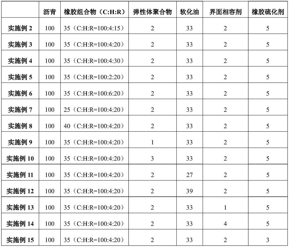
[0040] The difference from Example 1 is that the proportions of the components are different, and the specific proportions are shown in Table 1 below. In the table, C represents rubber powder, H represents rubber activator, and R represents rubber softener.
[0041] Table 1 is the component ratio table of Examples 2-15 and Comparative Examples 1-4
[0042]
[0043]
Embodiment 16
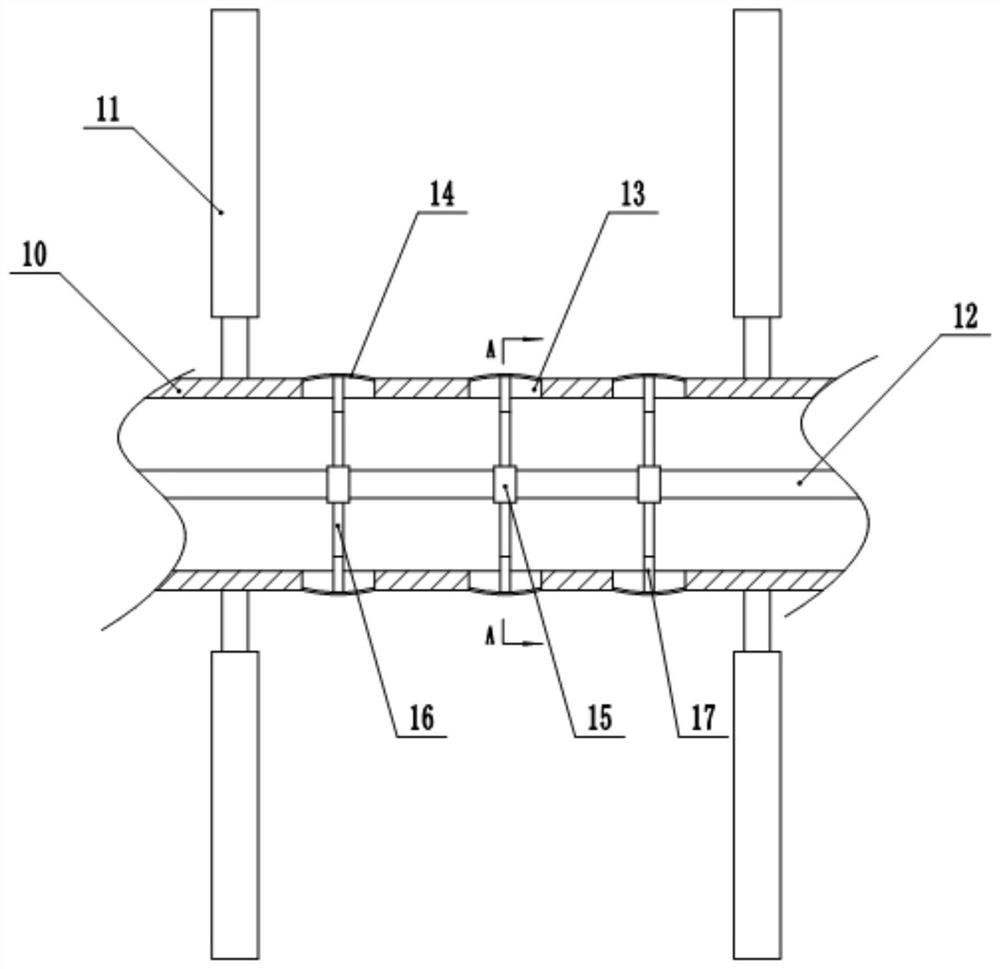
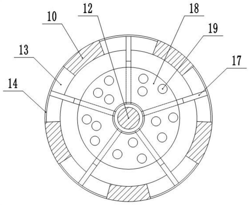
[0045] The difference from Example 1 is that a special stirring device is used in step S3 of Example 16, combined with figure 1 and figure 2 As shown, the special stirring equipment includes a horizontally fixed stirring drum, an inlet is provided at the left end of the stirring drum, an outlet is provided at the right end, and a stirring shaft 10 is rotatably connected in the stirring drum, wherein the stirring shaft 10 is hollow and arranged on two sides of the stirring shaft 10. Both ends are connected with pipes through rotary joints, and several stirring blades 11 are fixed on the stirring shaft 10, and the heating medium (gas, water, liquid metal, etc.) flows through the stirring shaft 10 through the pipes, thereby heating the stirring shaft 10 and stirring blades 11, A driving mechanism for driving the stirring shaft 10 to rotate is also provided.
[0046] A connecting rod 12 is slidably connected in the stirring shaft 10 . The connecting rod 12 is coaxially arranged ...
PUM
 Abstract
Description
Claims
Application Information
 - R&D
- Intellectual Property
- Life Sciences
- Materials
- Tech Scout
- Unparalleled Data Quality
- Higher Quality Content
- 60% Fewer Hallucinations
Browse by: Latest US Patents, China's latest patents, Technical Efficacy Thesaurus, Application Domain, Technology Topic, Popular Technical Reports.
© 2025 PatSnap. All rights reserved.Legal|Privacy policy|Modern Slavery Act Transparency Statement|Sitemap|About US| Contact US: help@patsnap.com


