Integrated reflux system with built-in heat recovery device and air purification device
What is AI technical title?
AI technical title is built by Patsnap AI team. It summarizes the technical point description of the patent document.
A technology of air purification device and heat recovery device
Inactive Publication Date: 2021-03-02
株式会社辰友E&T
View PDF7 Cites 1 Cited by
Summary
Abstract
Description
Claims
Application Information
AI Technical Summary
This helps you quickly interpret patents by identifying the three key elements:
Problems solved by technology
Method used
Benefits of technology
Problems solved by technology
[0013] However, the temperature of the inhaled effluent in the roll-to-roll dust collector is about 80-90°C, and most of the effluent exists in a gas-liquid state, so part of the effluent directly passes through the filter of the roll-to-roll dust collector and adheres to the metal On the oxide catalyst, the resulting whitening phenomenon leads to the disadvantage of the decomposition effect of ozone on the catalyst surface and the reduction of the amount of active oxygen generated, so after a long period of time, it will result in a bad smell or the decomposition and removal effect of volatile organic compounds. falling problem
Method used
Image
Click on the blue label to locate the original text in one second.
Reading with bidirectional positioning of images and text.
Examples
Embodiment 1
[0093] (Temperature reduction effect of polluted air by condenser)
[0094] ①Measurement method of temperature reduction effect
[0095] like image 3 As shown, the condenser is made in the radiator type, and the temperature of the polluted air discharged from the reflow furnace and passed through the heat exchanger is measured at the front end of the condenser and the rear end of the condenser, respectively, and the temperature reduction effect is compared and studied.
[0096] At this time, the return flow reaches the time point of normal operation, that is, the temperature is measured every 1 hour after starting 2 hours, based on the suction air volume of the blower is 3m 3 / min.
[0097] ②Measurement results of temperature reduction effect of polluted air
[0098] After the reflux reaches normal operating conditions, the temperature of the polluted air in the front end of the condenser is shown to be about 79.3°C at the time point of 1 hour, and the temperature of the ...
Embodiment 2
[0103] (Based on the removal effect of the effluent of the roll-to-roll dust collector)
[0104] ①Measuring method of removal effect of effluent
[0105] use Figure 4 In the roll-to-roll dust collector shown in the figure, the removal effect of the effluent contained in the polluted air generated during reflow soldering was measured with the naked eye.
[0106] The PCB board coated with solder paste is put into reflow, and the polluted air generated when the solder paste is melted in the furnace at about 250°C is the same as , and the effluent is condensed by a condenser, and the dust is collected in roll-to-roll The trapping occurs on the filter side of the device.
[0107] The measurement experiment of the removal effect of the effluent is determined by the number of PCB boards loaded, divided into 5 times, and the degree of capture on one side is measured respectively.
[0108] At this time, the suction air volume is set to 3m under the same conditions as 3 / min, and...
[0117] ①Measuring method of power consumption by adopting heat recovery device
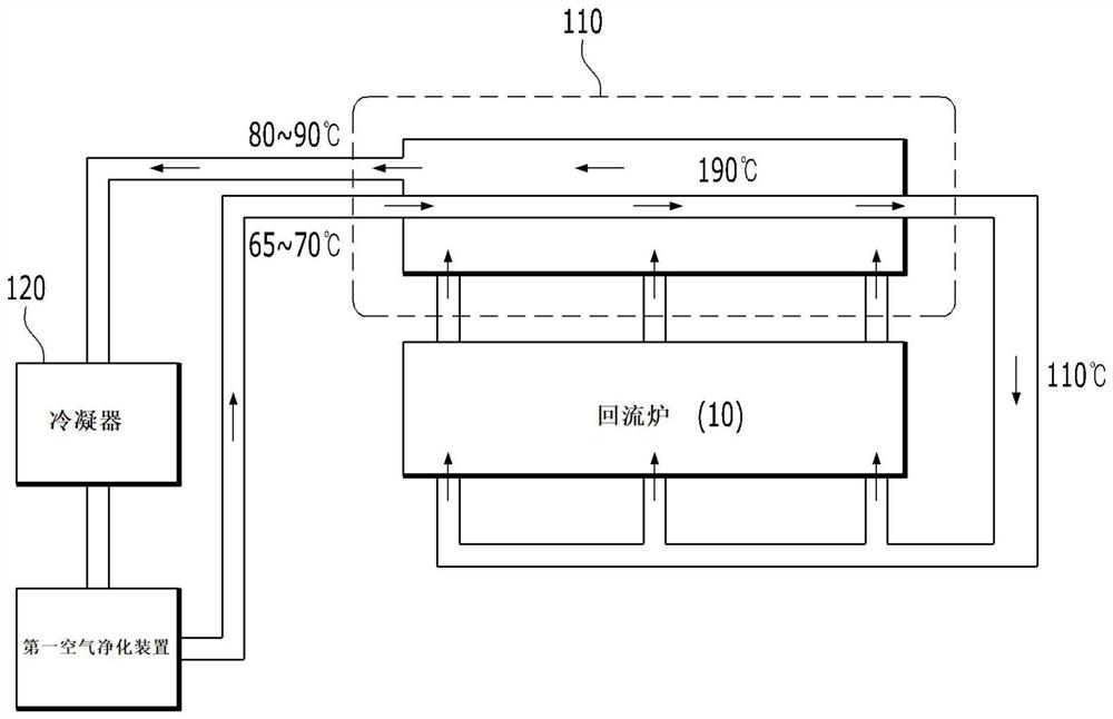
[0118] like figure 1 As shown in the schematic diagram of the heat recovery device, the air purified in real time based on the air purification device is heated up to about 110°C through the heat exchanger by using the polluted air with a high temperature of about 190°C discharged from the reflow furnace, and then re-introduced into the inside of the reflow furnace , so as to reduce the power consumption of reflux.
[0119] At this time, the suction air volume is set to 3m under the same conditions as in an industrial site 3 / min, use the integrated wattmeter to compare and measure the power consumption of the reflux before and after the use of the heat recovery device within 4 hours.
[0120] ②Measurement results of power consumption of reflow
[0121] refer to Figure 9 , before adopting the heat recovery device, the power consumpt...
PUM
Abstract
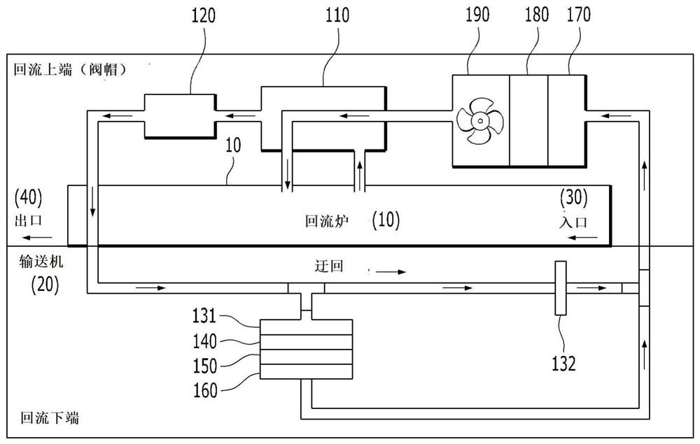
The present invention relates to a refluxsystem, and more particularly relates to an integrated refluxsystem with a built-in heat recovery device and an air purification device. The refluxsystem includes a condenser for condensing effluent and incorporates integrated devices such as a heat exchanger, a roll-to-roll dust collection device, and an air purification device, by recycling high-temperature heat generated in reflux and putting the high-temperature heat into a reflux furnace again, reflux energy consumption, namely electric quantity consumption, can be saved, and operation assemblylines in narrow and small spaces such as most factories can be prevented from being hindered. The technical feature of the present invention is that the reflux system comprises a heat recovery part (100) and a purification part (200), the heat recovery part (100) comprises a heat recovery device for recovering high-temperature heat from contaminated air discharged from a reflux furnace (10); and afirst air purification device used for purifying the contaminated air passing through the heat recovery device in real time and feeding the purified air into the reflux furnace (10) again; the purification part (200) comprises a second air purification device which purifies contaminated air discharged from an inlet part (30) and an outlet part (40) on the two sides of a reflux conveyor (20) in real time and discharges the contaminated air into the room (50).
Description
technical field [0001] The invention relates to a reflux system, which relates to an integrated reflux system with a built-in heat recovery device and an air purification device. The reflux system has a condenser for condensing effluent, a built-in heat exchanger, a roll-to-roll dust collection device, and an air purification device. Such an integrated device can save the energy consumption of reflow, that is, power consumption, by recovering the high-temperature heat generated in the reflow and re-injecting it into the reflow furnace, and can prevent the operation line in a small space such as most factories from being hindered. . Background technique [0002] Generally, surface mount technology (Surface Mount Technology, SMT) is a method of attaching surface mount components (Surface Mounted Components, SMC) that can be directly mounted on the surface of a printed circuit board (PCB) to a circuit. Use reflow soldering (Reflow Soldering) equipment, and realize by soldering...
Claims
Application Information
Patent Timeline
Application Date:The date an application was filed.
Publication Date:The date a patent or application was officially published.
First Publication Date:The earliest publication date of a patent with the same application number.
Issue Date:Publication date of the patent grant document.
PCT Entry Date:The Entry date of PCT National Phase.
Estimated Expiry Date:The statutory expiry date of a patent right according to the Patent Law, and it is the longest term of protection that the patent right can achieve without the termination of the patent right due to other reasons(Term extension factor has been taken into account ).
Invalid Date:Actual expiry date is based on effective date or publication date of legal transaction data of invalid patent.

