Balloon dilatation catheter

A technology for dilating catheters and balloons, which is applied in the field of medical devices, can solve problems such as general blood compatibility, low drug transfer rate, and complicated balloon structure, and achieve superior bending resistance, good control performance, and strong penetration performance. Effect

Pending Publication Date: 2021-03-05
尤东侠
View PDF16 Cites 5 Cited by
  • Summary
  • Abstract
  • Description
  • Claims
  • Application Information

AI Technical Summary

Problems solved by technology

[0004] 1. In order to ensure that the drug fully penetrates into the blood vessel or tissue, the DCB usually needs to be kept in a filling state for more than one minute, but the conventional coronary and peripheral vascular balloon dilation procedures limit the balloon expansion time (blocking blood flow time) to no more than a few minutes. ten seconds
The short contact time between DCB and diseased tissue and the low drug transfer rate need to be solved urgently
[0005] 2. Due to the insufficient binding force between the existing drug coating carrier material and the balloon material, the drug on the surface of the balloon is seriously lost during the intervention process
[0006] 3. The existing drug coating carrier materials have general hemocompatibility, which will have a negative effect on blood vessel healing
The balloon structure of this design is complex, the processing cost is very high, and many chemicals with poor hemocompatibility need to be used. For example, the filling agent is a kind of silicon dioxide or starch, and a hydrophilic polar monomer ( one of acrylic acid, methacrylic acid, acrylamide, acrylate, methacrylate, hydroxyethyl methacrylate, vinyl acetate, or acrylonitrile)

Method used


Image

  • Balloon dilatation catheter
  • Balloon dilatation catheter
  • Balloon dilatation catheter

Examples


Embodiment 1

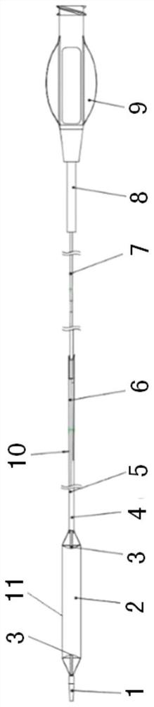
[0035] As shown in Figure 1, the balloon dilatation catheter of the embodiment includes: a soft head 1, a balloon 2, a blood flow guide groove 3, an inner tube 4, a distal outer tube 5, a transition tube 6, a hypotube 7, a stress support Tube 8, catheter handle 9, hydrophilic coating 10 and drug coating 11.

[0036] The combination of the soft head 1 and the inner tube 4 is placed and connected to the distal neck of the ball 2, and the inner tube 4 runs through the inner cavity of the distal outer tube 5 and the inner cavity of the balloon 2; the farthest part of the distal outer tube 5 The end is placed into the proximal neck of the bulb 2, and connected with it, so that the distal outer tube 5 and the bulb 2 are connected;

[0037] The catheter handle 9 is connected through the hypo tube 7, the transition tube 6 and the distal outer tube 5, and the liquid is injected from the filling cavity of the catheter handle 9 to fill the balloon 2 at high pressure. There is also a gap ...

Embodiment 2

[0047] On the basis of Example 1, the inner tube 4 of the balloon dilatation catheter of the present invention is as follows: Figure 5 As shown, it includes an outer proximal end 44, an outer distal end 43, a tubular middle metal mesh 42 and an inner layer 41 of an ultra-thin polytetrafluoroethylene tube (PTFE). The guide wire passes through the guide wire lumen 12 to reach the stenotic segment of the distal blood vessel.

[0048] The wall thickness of the outer material of the inner tube 4 gradually decreases or is equal from the proximal end to the far end, the outer diameter of the inner tube 4 also gradually decreases or is equal from the proximal end to the distal end, and the hardness of the inner tube 4 also decreases from the proximal end to the distal end. Decrease or equalize gradually.

[0049] The material of the inner tube outer layer proximal end 44 of the present invention is harder nylon or Pebax, and the inner tube outer layer distal end 43 material is less...

Embodiment 3

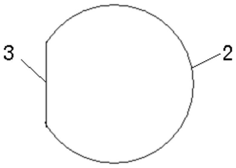
[0052] As shown in Figure 1, on the basis of Example 1, the surface of the balloon 2 is provided with a drug coating 11, and the drug coating 11 includes a bottom layer and an outer layer; wherein the bottom layer is a mixture of a drug and a drug carrier on the surface of the balloon; The outer layer is above the bottom layer and is a drug coating aid.

[0053] The drug is paclitaxel, rapamycin or a derivative of rapamycin, and the drug load is 1-6 micrograms per square millimeter, and it can also be a platelet-inhibiting drug, a vascular endothelialization drug or an anti-tumor drug. The drug coating thickness is between 5-100 microns. The drug carrier has good affinity with the balloon material and the blood vessel wall, such as biodegradable polymer materials, or linoleic acid and Omega-3 fatty acids. The drug coating assistant is urea, iopromide, alcohols or amino acids or polyunsaturated fatty acids.

[0054] When the balloon 2 of the present invention reaches the sten...


PUM


Abstract

The invention discloses a balloon dilatation catheter. The balloon dilatation catheter comprises a soft head, a balloon, an inner tube, a far-end outer tube, a transition tube, a hypotube and a catheter handle, wherein a combination body of the soft head and the inner tube is placed in and connected to the far-end neck part of the balloon; the inner tube penetrates through an inner cavity of the far-end outer tube and an inner cavity of the balloon; the farthest end of the far-end outer tube is placed in the near-end neck part of the balloon and is connected with the near-end neck part of theballoon; one or more blood flow guide grooves are formed in the surface of the balloon in the axial direction; and the inner tube is of a multi-layer structure, an outer layer is a macromolecule layerwith gradually changing hardness, a middle layer is a metal net, and an inner layer is PTFE. The balloon is provided with the blood flow guide grooves, so that blood flow cannot be completely blockedwhen the balloon is filled, and damage caused by ischemia of far-end blood vessels and tissue is avoided. The far ends of the balloon and the catheter are very smooth, and the balloon dilatation catheter is good in control performance and high in penetrating through performance, so that the surgery is quick, the cost is saved, and the risk to a patient is low.

Description

technical field [0001] The invention belongs to medical equipment, in particular to a balloon dilation catheter. Background technique [0002] Cerebrovascular disease is the most common major disease that threatens human life and health. Stroke is the leading cause of death in my country. Research data shows that 3.3 million new strokes occur in my country every year, and the number of stroke deaths is about 1.7 million every year. The annual treatment cost for this disease in the country is more than 10 billion yuan, which causes a heavy economic burden to the country and families. Cerebral aneurysm refers to an intracranial aneurysm with a hidden course and sudden onset. Once onset, disability and mortality are also high. Therefore, it is called an intracranial "uncertain time bomb" and is one of the most dangerous cerebrovascular diseases. one. There are as many as 200,000 new cerebral aneurysm patients in my country every year. For stroke and brain aneurysm, drug tre...

Claims


Application Information

Patent Timeline
Patent Type & Authority Applications(China)
IPC IPC(8): A61M25/10A61M31/00
CPCA61M25/104A61M31/00
Inventor 尤东侠
Owner 尤东侠
Why Eureka
Try Eureka