Wheel-legged robot and leg joint driving device thereof

A wheel-legged robot and driving device technology, which is applied to fluid pressure actuating devices, motor vehicles, mechanical equipment, etc., can solve the problems of low transmission efficiency of hydraulic systems, small output torque of joint driving devices, and complex system components.

Pending Publication Date: 2021-03-09
北京理工大学重庆创新中心 +1
View PDF0 Cites 1 Cited by
  • Summary
  • Abstract
  • Description
  • Claims
  • Application Information

AI Technical Summary

Problems solved by technology

[0005] 1. In the hydraulic system using the servo valve control cylinder as the joint actuator of the wheel-leg robot, a centralized pump station is used as the power source. In order to maintain a constant system pressure, the pump station part needs to use an overflow valve for overflow to maintain a constant pressure. , in this way, there is always overflow loss in the pump station part, which brings about the power loss of the system
[0006] 2. The servo valve control cylinder achieves precise output force / speed control of the hydraulic cylinder through the throttling of the servo valve. There is a large throttling power loss, the transmission efficiency of the hydraulic system is low, and the effective energy utilization rate of the robot is low.
Generally, when the wheel-legged robot is running, the output torque of its joint drive device needs to overcome its own gravity and inertial force, so a larger torque is required at this time, and a hydraulic actuator is required to drive it, which can achieve a higher power density. However, when the wheel-legged robot is performing a gait to cross obstacles, the joint drive device only needs to overcome the weight of the legs at this time, so the output torque of the joint drive device required at this time is relatively small. If the servo valve is used to control For the cylinder actuator, a huge pressure difference will be generated at the valve port of the servo valve, resulting in a large throttling loss
[0007] 3. The joint driving device system composed of servo valve control cylinder and centralized pumping station is complex, and the servo valve has poor resistance to oil pollution, resulting in poor reliability of the entire joint driving device
[0008] 4. The servo valve control cylinder is a rigid actuator composed of a servo valve and a hydraulic cylinder. When the wheel-legged robot encounters a protrusion while driving on the ground, it will produce an instantaneous force impact on the joint actuator. The servo valve control cylinder has no Passive buffer device, so under the impact of this instantaneous force, there will be an instantaneous pressure peak inside the hydraulic cylinder, which will damage the hydraulic components and seals
[0009] 5. The servo valve-controlled cylinder drive device cannot work normally after the robot system loses power, and it is inconvenient to transport
[0010] 6. The joint driving device system composed of servo valve control cylinder and centralized pumping station is complex, and the servo valve has poor resistance to oil pollution, resulting in poor reliability of the entire joint driving device

Method used


Image

  • Wheel-legged robot and leg joint driving device thereof
  • Wheel-legged robot and leg joint driving device thereof
  • Wheel-legged robot and leg joint driving device thereof

Examples


Embodiment 1

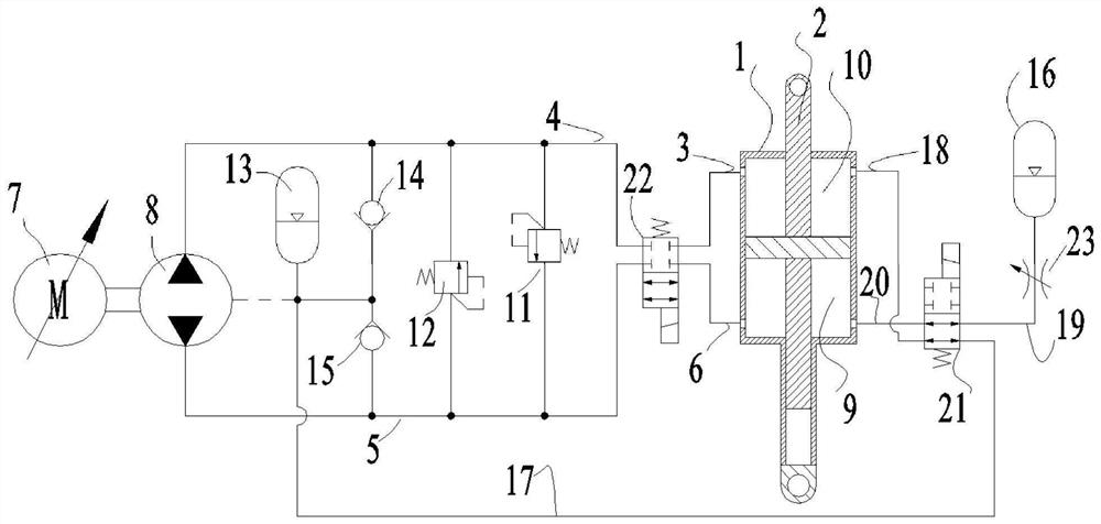
[0038] See attached Figure 1~5 . A driving device for leg joints of a wheel-leg robot, including a hydraulic control system; the hydraulic control system includes a hydraulic cylinder 1, a piston rod 2, a main oil circuit, a secondary oil circuit, a servo motor 7 and a hydraulic pump 8; the hydraulic cylinder 1 is provided with a load chamber 9 and a non-load chamber 10; the piston rod 2 separates the load chamber 9 and the non-load chamber 10; the servo motor 7 is used to drive the hydraulic pump 8; the non-load chamber 10, the main oil circuit , the hydraulic pump 8 , the secondary oil circuit and the bearing chamber 9 are connected in sequence; the elongation of the piston rod 2 relative to the hydraulic cylinder 1 changes with the hydraulic oil capacity in the bearing chamber 9 and the non-bearing chamber 10 . It can be seen from the above structure that if the circuit formed by the non-bearing chamber 10, the main oil circuit, the hydraulic pump 8, the secondary oil cir...

Embodiment 2

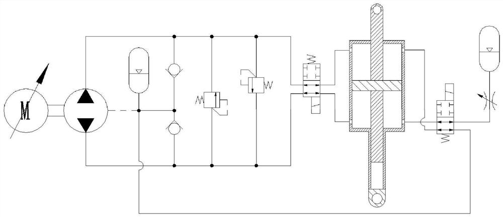
[0050] See attached Figure 4~6 . A driving device for leg joints of a wheel-leg robot, including a hydraulic control system; the hydraulic control system includes a hydraulic cylinder 1, a piston rod 2, a main oil circuit, a secondary oil circuit, a servo motor 7 and a hydraulic pump 8; the hydraulic cylinder 1 is provided with a load chamber 9 and a non-load chamber 10; the piston rod 2 separates the load chamber 9 and the non-load chamber 10; the servo motor 7 is used to drive the hydraulic pump 8; the non-load chamber 10, the main oil circuit , the hydraulic pump 8 , the secondary oil circuit and the bearing chamber 9 are connected in sequence; the elongation of the piston rod 2 relative to the hydraulic cylinder 1 changes with the hydraulic oil capacity in the bearing chamber 9 and the non-bearing chamber 10 . It can be seen from the above structure that if the circuit formed by the non-bearing chamber 10, the main oil circuit, the hydraulic pump 8, the secondary oil cir...

Embodiment 3

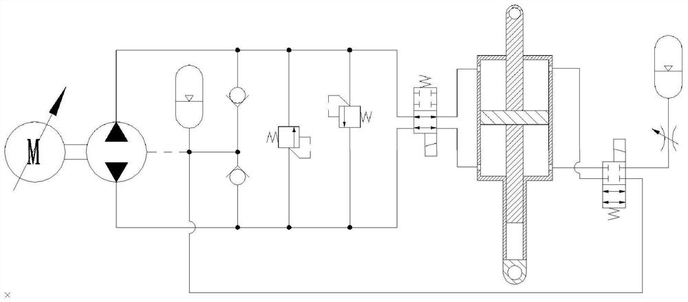
[0062] See attached Figure 7-9 . A driving device for leg joints of a wheel-leg robot, including a hydraulic control system; the hydraulic control system includes a hydraulic cylinder 1, a piston rod 2, a main oil circuit, a secondary oil circuit, a servo motor 7 and a hydraulic pump 8; the hydraulic cylinder 1 is provided with a load chamber 9 and a non-load chamber 10; the piston rod 2 separates the load chamber 9 and the non-load chamber 10; the servo motor 7 is used to drive the hydraulic pump 8; the non-load chamber 10, the main oil circuit , the hydraulic pump 8 , the secondary oil circuit and the bearing chamber 9 are connected in sequence; the elongation of the piston rod 2 relative to the hydraulic cylinder 1 changes with the hydraulic oil capacity in the bearing chamber 9 and the non-bearing chamber 10 . It can be seen from the above structure that if the circuit formed by the non-bearing chamber 10, the main oil circuit, the hydraulic pump 8, the secondary oil cir...


PUM


Abstract

The invention discloses a wheel-legged robot and a leg joint driving device thereof, and belongs to the technical field of wheel-legged robots. The wheel-legged robot comprises a hydraulic control system, wherein the hydraulic control system comprises a hydraulic cylinder, a piston rod, a main oil path, a secondary oil path, a servo motor and a hydraulic pump; a bearing cavity and a non-bearing cavity are formed in the hydraulic cylinder; the piston rod is used for separating the bearing cavity from the non-bearing cavity; the servo motor is used for driving the hydraulic pump; the non-bearingcavity, the main oil path, the hydraulic pump, the secondary oil path and the bearing cavity communicate with one another in sequence; and the elongation of the piston rod relative to the hydraulic cylinder is changed along with change of the capacity of hydraulic oil in the bearing cavity and the non-bearing cavity. According to the wheel-legged robot and the leg joint driving device thereof, overflow loss and throttling loss are avoided, the system power is saved, the transmission efficiency of the hydraulic system is high, the energy utilization rate is high, the buffering performance is good, and the service life is long.

Description

technical field [0001] The invention belongs to the technical field of wheel-leg robots, and in particular relates to a wheel-leg robot and a driving device for leg joints thereof. Background technique [0002] The wheel-legged robot refers to adding wheels to the end of the robot legs. This kind of robot fully combines the advantages of wheels and legs. pass in a structured environment. Compared with the legged robot, it has a faster traveling speed in the road environment, so the research on the wheel-legged robot has received more and more attention. [0003] At present, research on wheel-legged robots is mainly focused on small wheel-legged robot platforms. The robot body and load capacity are small, and the combination of motor and reducer can be used to drive the leg joints; for medium / large wheel-legged robots The drive of the leg joints is driven by a servo valve control cylinder. The servo valve is installed on the hydraulic cylinder, and the piston rod of the hyd...

Claims


Application Information

Patent Timeline
Patent Type & Authority Applications(China)
IPC IPC(8): F15B11/08F15B1/02F15B13/044F15B13/02F15B13/08F15B21/08B62D57/028
CPCB62D57/028F15B1/02F15B11/08F15B13/027F15B13/0416F15B13/044F15B13/08F15B13/085F15B21/08F15B2013/0448F15B2211/20515
Inventor 胡小东徐彬秦也辰刘辉项昌乐杨海洋刘春桃
Owner 北京理工大学重庆创新中心
Why Eureka
Try Eureka