A Low Power Consumption, High DC Bias Core and Its Application
A high DC bias, low power consumption technology, applied in magnetic core manufacturing, inductor/transformer/magnet manufacturing, preventing/reducing unwanted electrical/magnetic effects, etc. Increase energy consumption and other problems, achieve low power consumption, eliminate hysteresis loss and residual loss, and reduce eddy current loss
- Summary
- Abstract
- Description
- Claims
- Application Information
AI Technical Summary
Problems solved by technology
Method used
Image
Examples
Embodiment 1
[0023] The preparation method of the present embodiment of a low-power, high DC bias core, comprising the following steps:
[0024] (1) The synthesis of manganese-zinc ferrite nanoparticles by high-temperature pyrolysis method, with a particle diameter of 20 nanometers;
[0025] (2) Ethyl orthosilicate hydrolysis method was used to uniformly coat the surface of manganese zinc ferrite nanoparticles with a layer of silicon oxide, with a thickness of 5 nanometers;
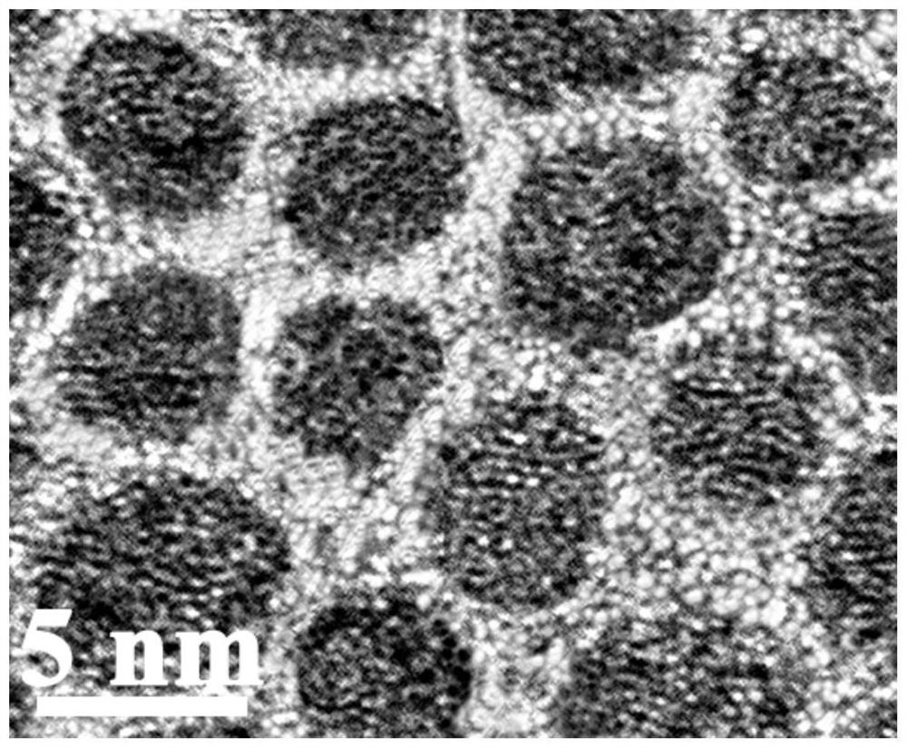
[0026] (3) Using the discharge plasma sintering method, the above-mentioned manganese zinc ferrite nanoparticles coated with silica are rapidly sintered at 600 °C to ensure that the particle size is not long, and the core is obtained after consolidation. as Figure 1 As shown, the bright part of the figure is a non-magnetic insulating matrix (i.e., silicon oxide), and the dark part is a manganese-zinc ferrite nanoparticle.
[0027] Among them, the volume fraction of manganese-zinc ferrite nanoparticles in the core is 75%. ...
Embodiment 2
[0031] The preparation method of the present embodiment of a low-power, high DC bias core, comprising the following steps:
[0032] (1) Iron-nickel nanoparticles are synthesized by DC arc plasma method, and the particle diameter is 8 nanometers;
[0033] (2) The butyl titanate hydrolysis method is used to uniformly coat the surface of the iron-nickel nanoparticles with a layer of titanium oxide, with a thickness of 2 nanometers;
[0034] (3) The hot pressing sintering method is adopted to hot press sinter the above-mentioned iron-nickel nanoparticles coated with titanium oxide at 800 °C to ensure that the particle size is not long, and the core is obtained after consolidation.
[0035] Among them, the volume fraction of manganese-zinc ferrite nanoparticles in the core is 65%.
[0036] After testing, the resistivity of the consolidated core material is 0.8×10 4 μΩ·cm, permeability of 200, DC bias performance of 80% (100mT), loss at 500KHz, 150mT is 220KW / m 3 , below 300KW / m at 1MHz...
Embodiment 3
[0039] The preparation method of the present embodiment of a low-power, high DC bias core, comprising the following steps:
[0040] (1) The iron nanoparticles are synthesized by thermal reduction method, and the particle diameter is 6 nanometers;
[0041] (2) Disperse iron nanoparticles in liquid phenolic resin;
[0042] (3) Heating up to 300 ° C, the phenolic resin solidifies, the iron nanoparticles are uniformly coated by the phenolic resin, and the nanoparticles are not large in size, and the core is obtained after consolidation.
[0043] Among them, the volume fraction of iron nanoparticles in the magnetic core is 50%.
[0044] After testing, the resistivity of the consolidated core material is 3×10 5 μΩ·cm, permeability of 70, DC bias performance of 63% (100mT), loss at 500KHz, 150mT is 340KW / m 3 , below 430KW / m at 1MHz, 10mT 3 , at 3MHz, 50mT below 255KW / m 3 , at 10MHz, 5mT below 43KW / m 3 。
[0045] The core of the present embodiment can achieve low power consumption and high ...
PUM
| Property | Measurement | Unit |
|---|---|---|
| electrical resistivity | aaaaa | aaaaa |
| electrical resistivity | aaaaa | aaaaa |
| frequency | aaaaa | aaaaa |
Abstract
Description
Claims
Application Information
 - R&D
- Intellectual Property
- Life Sciences
- Materials
- Tech Scout
- Unparalleled Data Quality
- Higher Quality Content
- 60% Fewer Hallucinations
Browse by: Latest US Patents, China's latest patents, Technical Efficacy Thesaurus, Application Domain, Technology Topic, Popular Technical Reports.
© 2025 PatSnap. All rights reserved.Legal|Privacy policy|Modern Slavery Act Transparency Statement|Sitemap|About US| Contact US: help@patsnap.com

