A thin-gauge martensitic steel strip and its manufacturing method

A technology of martensitic steel and manufacturing method, applied in the direction of manufacturing tools, heat treatment process control, heat treatment equipment, etc., can solve the problems of plate shape deterioration, uneven cooling, uneven microstructure, etc., and achieve energy consumption and CO2 emission reduction , production line investment cost reduction, the effect of achieving sustainable development

Active Publication Date: 2022-06-24
BAOSHAN IRON & STEEL CO LTD
View PDF16 Cites 0 Cited by
  • Summary
  • Abstract
  • Description
  • Claims
  • Application Information

AI Technical Summary

Problems solved by technology

At the same time, the contact of high-temperature strip steel with cooling water will cause many problems: first, water spots (rust spots) will be formed on the surface of the strip steel, which will affect the surface quality; second, the cooling water used for laminar flow cooling or spray cooling It is easy to cause uneven local cooling on the surface of the strip, resulting in uneven microstructure inside the strip, resulting in uneven properties of the strip and affecting product quality; third, uneven local cooling on the surface of the strip will cause deterioration of the shape of the strip , affecting the shape quality
[0014] However, due to the rapid solidification process characteristics of thin strip continuous casting, the produced steel generally has the problems of uneven structure, low elongation, high yield ratio, and poor formability; The grains have obvious inhomogeneity, which will lead to the inhomogeneous structure of the final product obtained after austenite transformation, resulting in unstable performance of the product
Therefore, it is difficult and challenging to use a thin strip continuous casting production line to produce some high-strength products required by the automotive industry and the petrochemical industry. Therefore, when using thin strip continuous casting to produce high-strength martensitic steel, the traditional composition should be copied Craftsmanship cannot be produced and requires a breakthrough in composition and craftsmanship

Method used


Image

  • A thin-gauge martensitic steel strip and its manufacturing method
  • A thin-gauge martensitic steel strip and its manufacturing method
  • A thin-gauge martensitic steel strip and its manufacturing method

Examples


Embodiment Construction

[0079] The present invention will be further described below with examples, but these examples do not limit the present invention by any means. Any changes made by those skilled in the art in the implementation of the present invention under the inspiration of this specification will fall within the protection scope of the claims of the present invention.

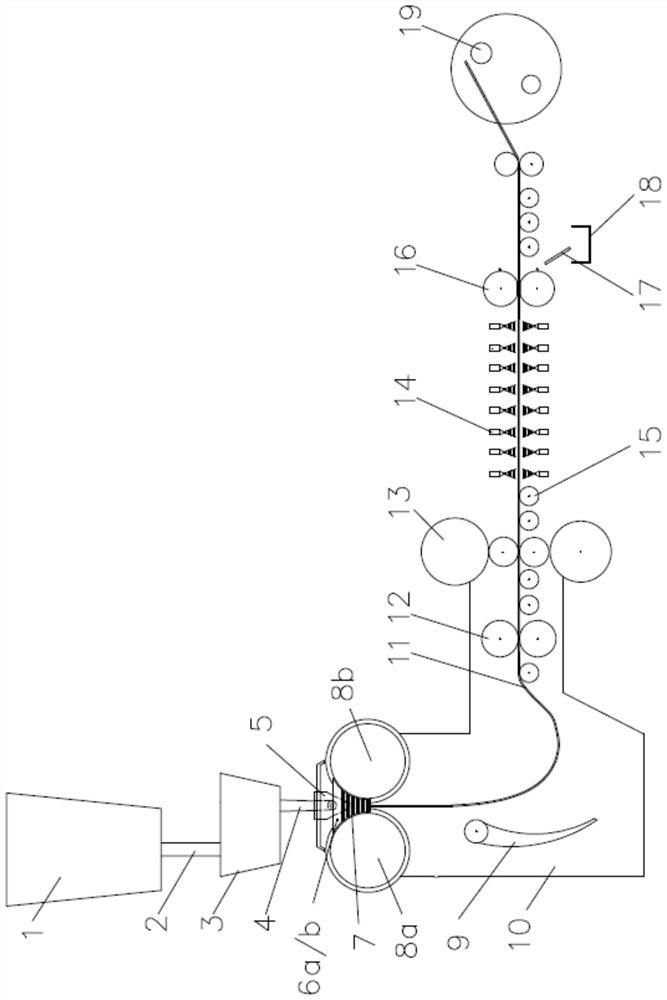
[0080] see figure 1 , the molten steel that conforms to the chemical composition design of the present invention is directly poured into a crystallization by two relatively rotating and rapid cooling through the large ladle long nozzle 2, the tundish 3, the submerged nozzle 4 and the distributor 5. In the molten pool 7 surrounded by the rolls 8a, 8b and the side sealing plate devices 6a, 6b, the molten steel solidifies on the circumferential surface of the rotation of the crystallization rolls 8a, 8b, and then forms a solidification shell and gradually grows. Then, the gap between the two crystallization rolls is the smalle...


PUM

PropertyMeasurementUnit
thicknessaaaaaaaaaa
yield strengthaaaaaaaaaa
tensile strengthaaaaaaaaaa

Abstract

A thin-gauge martensitic steel strip and its manufacturing method, the composition weight percent of which is: C: 0.16‑0.26%, Si: 0.1‑0.5%, Mn: 0.4‑1.7%, P≤0.02%, S≤0.007% , N: 0.004‑0.010%, Als: <0.001%, total oxygen [O] T : 0.007‑0.020%; the balance is Fe and other unavoidable impurities, and at the same time: containing one or both of Cu: 0.1‑0.6% or Sn: 0.005‑0.04%; containing Nb: 0.01‑0.08%, Mo: one or two of 0.1‑0.4%; Mn / S>250. The invention utilizes residual Sn, Cu and other elements in scrap steel to smelt molten steel, and selectively adds microalloying elements such as Nb / Mo to the steel; during the smelting process, the alkalinity of slag, the type of inclusions in steel and the melting point are controlled , free oxygen content in molten steel, and acid-soluble aluminum Als content; then twin-roll thin strip continuous casting is performed to cast the cast strip, which is obtained by online hot rolling and rapid cooling by gas atomization.

Description

technical field [0001] The invention belongs to a continuous casting process, in particular to a thin-gauge martensitic steel strip and a manufacturing method thereof. Background technique [0002] In the traditional steel production process, tin (Sn) and copper (Cu) are typical residual elements or harmful elements in steel. It is very difficult and expensive to fully remove Sn and Cu during the steelmaking process. Once the steel contains Sn , Cu, basically can not be completely eliminated, only by diluting molten steel to reduce the content of Sn, Cu, which all lead to the increase of the smelting cost of iron and steel products. [0003] In recent years, due to the continuous recycling of scrap steel, there are more and more scrap steel resources, and electricity prices have continued to decrease. Sn and Cu in steel are easy-to-segregate elements, which are easily enriched at the grain boundary to cause defects such as cracks. Therefore, the content of Sn and Cu element...

Claims


Application Information

Patent Timeline
Patent Type & Authority Patents(China)
IPC IPC(8): C22C38/16C22C38/12C22C38/06C22C38/04C22C38/02C22C33/04B22D11/06C21D1/74C21D8/02C21D11/00C21D1/00
CPCC22C38/16C22C38/12C22C38/06C22C38/04C22C38/02C22C38/008C22C38/002C22C38/001C22C33/04B22D11/0622B22D11/0682C21D1/74C21D8/0205C21D8/0226C21D11/005C21D1/00C21D2211/002C21D2211/008
Inventor 吴建春方园
Owner BAOSHAN IRON & STEEL CO LTD
Why Eureka
Try Eureka