Back pipe for casting rotary target material and manufacturing method thereof

A technology of rotating target and back tube, which is applied in the improvement of process efficiency, metal material coating process, ion implantation plating, etc. and other problems, to achieve the effect of good thermal conductivity, large sputtering power, and less target impurities

Active Publication Date: 2021-03-19
JIANGYIN ENTRET COATING TECH
View PDF8 Cites 0 Cited by
  • Summary
  • Abstract
  • Description
  • Claims
  • Application Information

AI Technical Summary

Problems solved by technology

[0004] However, this method has the following problems: 1. It takes a certain period of time for the melt of the target material to fully infiltrate the surface of the nickel-aluminum layer (only after infiltration can the two be combined to achieve alloying, thereby high bonding strength), and The infiltration process of each part is inconsistent. First, some points start to infiltrate, then gradually expand from the point to the surface, and finally the entire outer surface is completely infiltrated, which leads to a long time for most surfaces to infiltrate, and a large amount of nickel and aluminum elements Dissolved into the target material melt, resulting in excessive nickel and aluminum element content in the target, and the final target purity is unqualified; 2. The rotating target is installed on the vacuum magnetron sputtering coating equipment, and the tube inside the back tube A magnetic rod is placed in the cavity, and the magnetic field of the magnetic rod penetrates the stainless steel back tube, the nickel-aluminum layer and the target material to control the charged ions (usually argon ions) outside the target to bombard the target surface, so that the target material is atomized However, the nickel-aluminum layer is a magnetic material, which will form a certain degree of shielding effect on the magnetic bar, thereby weakening the magnetic field outside the rotating target and making the sputtering effect worse

Method used


Image

  • Back pipe for casting rotary target material and manufacturing method thereof
  • Back pipe for casting rotary target material and manufacturing method thereof

Examples


Embodiment 1

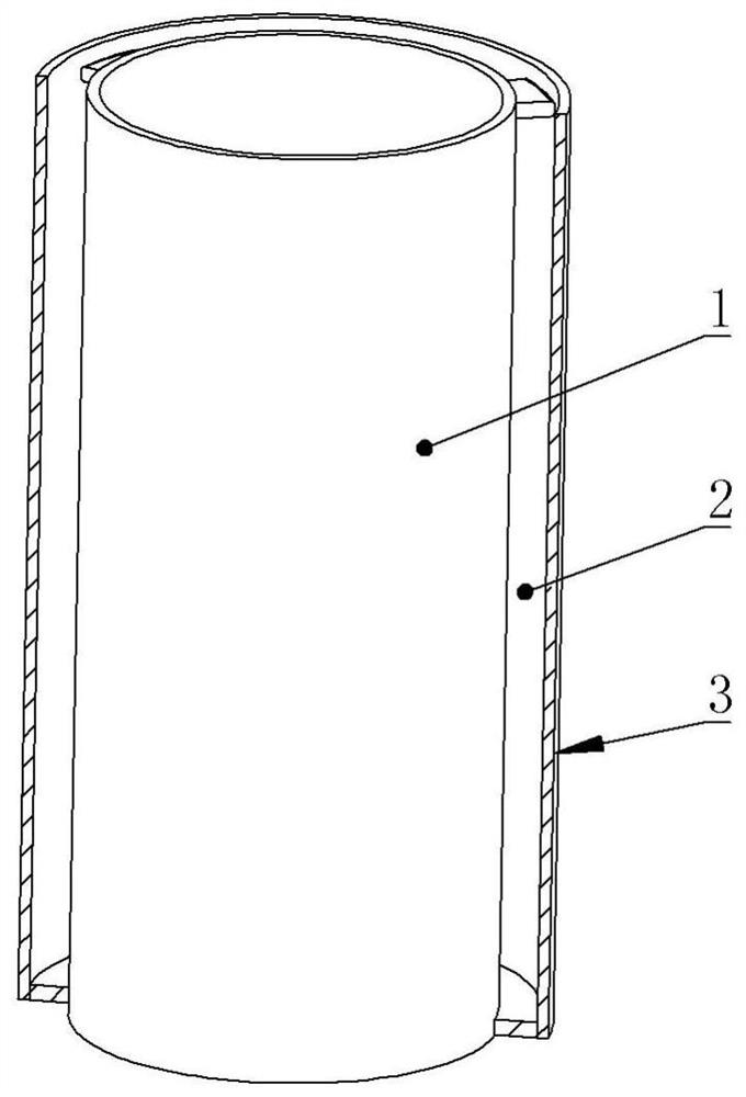
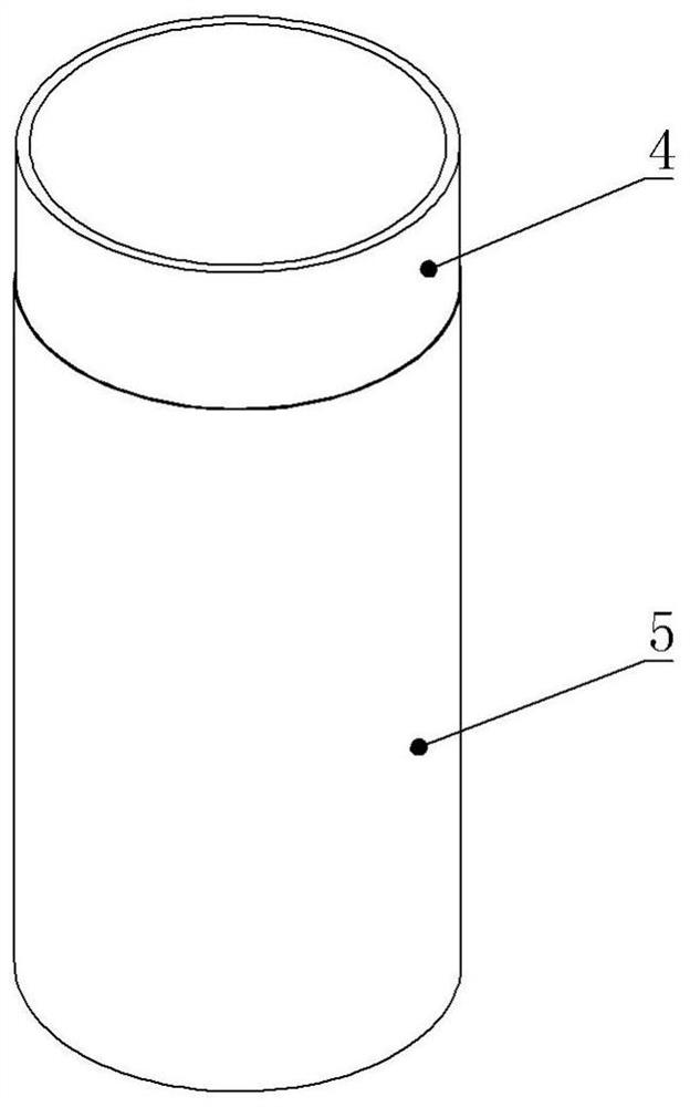
[0027] A back tube for casting a rotating target, comprising a stainless steel tube 4, the exterior of the stainless steel tube 4 is electroplated with a nickel layer 5, the thickness of the nickel layer 5 is 0.005 mm, and the surface roughness of the nickel layer 5 is Ra3.2~Ra6.3, the surface of the nickel layer 5 has a tin infiltrated layer. The grade of the stainless steel pipe is 304, 304L, 316 or 316L.

[0028] The production method of the back pipe for casting a rotating target, the steps are:

[0029] a. Clean the outer surface of the stainless steel pipe to remove dust and oil, and then use a P120 abrasive belt to polish the outer surface so that the roughness of the outer surface is Ra3.2-Ra6.3. In order to improve the grinding efficiency, a grinding machine equipped with a P120 annular abrasive belt can be used for grinding.

[0030] b. Put the stainless steel tube obtained in step a into an electroplating tank for nickel electroplating, so that a nickel layer is a...

Embodiment 2

[0039] This embodiment is basically the same as embodiment 1, except that in the step f of the production method, the tin seeping solution is applied to the outer surface of the stainless steel tube obtained in step e and the holding time is 80 minutes. At this time, the tin penetration time is longer, and the area occupied by the tin layer on the surface of the nickel layer becomes larger, reaching more than 40%, and the part is even connected into sheets, and the thickness of the tin layer is less than 0.002 mm.

[0040] The back tube of this embodiment is used for target production, and the total amount of nickel and tin infiltrated into the target material accounts for less than 0.009% by weight of the target material. However, due to the large proportion of the tin layer, the soaking time is shortened by more than 70% than that of the tin-free layer.

Embodiment 3

[0042] A back tube for casting a rotating target, comprising a stainless steel tube 4, the exterior of the stainless steel tube 4 is electroplated with a nickel layer 5, the thickness of the nickel layer 5 is 0.02 mm, and the surface roughness of the nickel layer 5 is Ra3.2~Ra6.3, the surface of the nickel layer 5 has a tin infiltrated layer. The grade of the stainless steel pipe is 304, 304L, 316 or 316L.

[0043] The production method and steps of the back tube for casting a rotating target in this embodiment are the same as those in Embodiment 1.

[0044] Using the back tube of this embodiment to produce the target material has a higher purity than the back tube of the prior art under other conditions being the same. In addition, since the thickness of the nickel layer is 0.02 mm, it is still very thin compared with the 0.5 mm nickel-aluminum layer of the prior art, and the shielding effect on the magnetic field is small, and the sputtering effect is better. Moreover, the...


PUM

PropertyMeasurementUnit
thicknessaaaaaaaaaa
thicknessaaaaaaaaaa
thicknessaaaaaaaaaa

Abstract

The invention relates to the technical field of rotary target material manufacturing, in particular to a back pipe for casting a rotary target material. The back pipe comprises a stainless steel pipe,wherein a nickel layer is electroplated outside the stainless steel pipe, the thickness of the nickel layer ranges from 0.005 mm to 0.1 mm, the surface roughness of the nickel layer ranges from Ra3.2to Ra6.3, and a tin impregnation layer is arranged on the surface of the nickel layer. The manufacturing method comprises the following steps of, cleaning the surface of the stainless steel pipe, polishing the stainless steel pipe, electroplating the nickel layer on the surface of the stainless steel pipe, carrying out annealing, treating the outer surface by using an acidic solution, treating the outer surface by using a tin impregnation solution, cleaning and airing to obtain the back pipe for casting the rotary target material. The rotary target material produced by the back tube has few impurities, has a small shielding effect on a magnetic field, and has a good sputtering effect.

Description

technical field [0001] The invention relates to the technical field of manufacturing a rotating target, in particular to a back tube for casting a rotating target and a manufacturing method thereof. Background technique [0002] Compared with the planar target, the rotating target has the advantages of high utilization rate and high sputtering efficiency. The current low melting point rotating targets, such as rotating tin targets, rotating zinc-tin targets, rotating zinc-aluminum targets and rotating zinc-tin-antimony targets, are generally produced by casting. The rotating target produced by the casting process has the advantages of high density, low oxygen and nitrogen content, good thermal conductivity, etc., and the equipment is simple and the production cost is low. However, tin, zinc tin and other materials have low strength and are easy to deform, so they must be cast on the stainless steel back pipe. [0003] The current production principle of rotating target is ...

Claims


Application Information

Patent Timeline
Patent Type & Authority Applications(China)
IPC IPC(8): C25D7/04C25D3/12C25D5/50C25D5/48C23C10/24C23C14/35
CPCC25D7/04C25D3/12C25D5/50C25D5/48C23C10/24C23C14/3414C23C14/35Y02P10/20
Inventor 胡习光
Owner JIANGYIN ENTRET COATING TECH
Why Eureka
Try Eureka