Pump valve coordinated multi-actuator electro-hydraulic system and control method thereof

A multi-actuator and electro-hydraulic control system technology, which is applied in the field of hydraulic transmission, can solve the problems of low installed power and achieve the effects of eliminating throttling loss, reducing installed power, and reducing valve port throttling loss

Active Publication Date: 2021-04-13
TAIYUAN UNIV OF TECH
View PDF11 Cites 15 Cited by
  • Summary
  • Abstract
  • Description
  • Claims
  • Application Information

AI Technical Summary

Problems solved by technology

[0005] In order to solve the problems and deficiencies existing in the existing multi-actuator system, the present invention aims to provide a system with small installed power, easy to compensate the asymmetric flow rate of asymmetric hydraulic cylinders, and capable of distributing system flow and recovering system kinetic energy with extremely low pressure loss. The pump-valve cooperative multi-actuator electro-hydraulic system and its control method

Method used


Image

  • Pump valve coordinated multi-actuator electro-hydraulic system and control method thereof
  • Pump valve coordinated multi-actuator electro-hydraulic system and control method thereof
  • Pump valve coordinated multi-actuator electro-hydraulic system and control method thereof

Examples


Embodiment 1

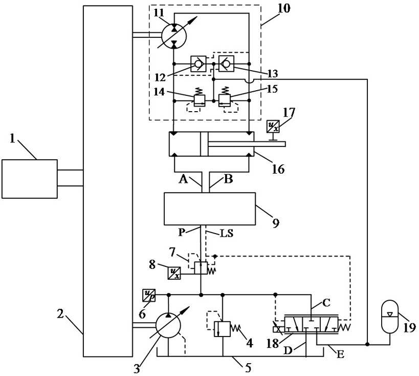
[0053] Figure 5 The schematic circuit diagram of the application of the pump valve cooperative multi-actuator electro-hydraulic system of the present invention to the complete machine of the excavator is given, including the prime mover 1, the transfer case 2, the stick hydraulic cylinder 16-1, and the bucket hydraulic cylinder 16-2 , the first boom hydraulic cylinder 16-3, the second boom hydraulic cylinder 16-4, the swing motor 28, the first distributed pump control unit 10-1, the second distributed pump control unit 10-2, the third distribution Type pump control unit 10-3, fourth distributed pump control unit 10-4, hydraulic cylinders are equipped with displacement sensors 17. Among them, the arm hydraulic cylinder, the bucket hydraulic cylinder, the boom hydraulic cylinder, and the swing motor are respectively controlled by the first distributed pump control unit 10-1, the second distributed pump control unit 10-2, and the third distributed pump control unit. 10-3. Drive...

Embodiment 2

[0067] Image 6 The schematic circuit diagram of the application of the pump-valve cooperative multi-actuator electro-hydraulic system of the present invention to the excavator is given. The composition and working principle of the pump-valve cooperative multi-actuator electro-hydraulic system in this embodiment are the same as those in Embodiment 1. What’s more, the first boom hydraulic cylinder 16-3 and the second boom hydraulic cylinder 16-4 are replaced by the first three-chamber hydraulic cylinder 16-5 and the second three-chamber hydraulic cylinder 16-6, and further energy storage Energy device 34, the first IV relief valve 35. The three-chamber hydraulic cylinder includes a working volume A, a working volume B, and an energy storage volume C. The working volume of the three-chamber hydraulic cylinder is connected with the distributed pump control unit 10-3, and the matching control valve group working oil port A , Working oil port B communicates with working chamber A ...


PUM


Abstract

The invention relates to a pump valve coordinated multi-actuator electro-hydraulic control system. The pump valve coordinated multi-actuator electro-hydraulic control system comprises a prime motor, a transfer case, one or more hydraulic cylinders, distributed pump control units and a hydraulic cylinder displacement sensor, a centralized flow power compensation unit is additionally arranged for the distributed pump control units, and the centralized flow power compensation unit comprises a main hydraulic pump, a first overflow valve and an oil tank, a first pressure sensor, a pressure compensator, a control valve set, a bypass proportional valve and an oil supplementing energy accumulator. A valve core displacement sensor is additionally arranged on the pressure compensator. Each distributed pump control unit comprises a two-way variable pump/motor, a first oil supplementing one-way valve, a second oil supplementing one-way valve, a second overflow valve and a third overflow valve. By additionally arranging the centralized flow power compensation unit, the asymmetric flow of all the distributed pump control units is subjected to centralized compensation and power supplementation, various flow compensation auxiliary elements are not needed, a small-power pump control system drives and drags a high-power actuator, and the total installed power of the pump control multi-actuator system is remarkably reduced.

Description

technical field [0001] The invention relates to the field of hydraulic transmission, in particular to a pump-controlled multi-actuator system, which is a multi-actuator system that compensates flow and power in a centralized manner, uses a pump control circuit to eliminate load differences among actuators, and distributes power and recovers kinetic potential energy based on torque coupling. system and its control method. Background technique [0002] In recent years, as the world's energy shortage and environmental pollution problems continue to intensify, research on energy conservation and emission reduction of hydraulic systems has become an hotspot. The existing positive flow, negative flow and load sensing technologies have played an important role in improving the energy efficiency of the system, but the system still uses a centralized power source for energy supply, multi-way valves for power distribution, and the output pressure of the pump must match the highest lo...

Claims


Application Information

Patent Timeline
Patent Type & Authority Applications(China)
IPC IPC(8): F15B1/02F15B11/16F15B13/06F15B15/28F15B19/00E02F9/22
CPCF15B11/167F15B13/06F15B1/02F15B15/2815F15B19/00E02F9/2264E02F9/2267E02F9/2271F15B2211/20546
Inventor 权龙乔舒斐李运帷张晓刚王波
Owner TAIYUAN UNIV OF TECH
Why Eureka
Try Eureka