
Miniaturized teapot-shaped ultra-wideband antenna

An ultra-wideband antenna and teapot technology, applied in the field of wireless communication, can solve the problems of large volume, small bandwidth, and reduce the overall unit section, and achieve the effect of good radiation characteristics, small size, and compact structure

Pending Publication Date: 2021-05-07
LIAONING TECHNICAL UNIVERSITY
View PDF2 Cites 2 Cited by
  • Summary
  • Abstract
  • Description
  • Claims
  • Application Information

AI Technical Summary

Problems solved by technology

[0004] The Chinese invention patent with the application number 201911380795.2 proposes an external antenna for ultra-broadband terminal products. Its detachable top cover is convenient for adjusting the radiation antenna on the machine. By adjusting the rotation of the threaded rod, the parasitic radiation antenna and the main radiation antenna can be exposed. To achieve the purpose of intelligent opening, but the working frequency band of the antenna is 700MHz~6GHz, and the bandwidth is relatively small; the Chinese invention patent application number is 201810410717.1, which proposes a miniaturized low-profile ultra-wideband logarithmic periodic monopole array antenna, using 22 Two monopoles working at different frequencies to achieve ultra-broadband characteristics. The radiation pattern points to the end-fire direction of the array. Some monopoles introduce capacitance by loading plate capacitors on the top to reduce the profile of the overall unit. The electric constant dielectric substrate realizes the miniaturization of the feeder and the overall structure, and the bandwidth of the antenna is 1-10.7GHz, which completely covers the range defined by the ultra-wideband antenna specified by the FCC, but the size of the antenna is 520mm×16mm×18.4mm, which is relatively large

Method used


Image

  • Miniaturized teapot-shaped ultra-wideband antenna
  • Miniaturized teapot-shaped ultra-wideband antenna
  • Miniaturized teapot-shaped ultra-wideband antenna

Examples


Embodiment Construction

[0033]The specific implementation of the present invention will be described in detail below in conjunction with the accompanying drawings. As a part of this specification, the principles of the present invention will be described through examples. Other aspects, features and advantages of the present invention will become clear through the detailed description. In the referenced drawings, the same reference numerals are used for the same or similar components in different drawings.

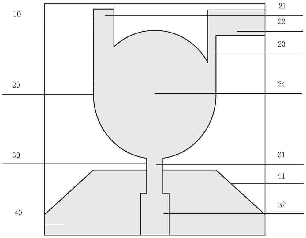
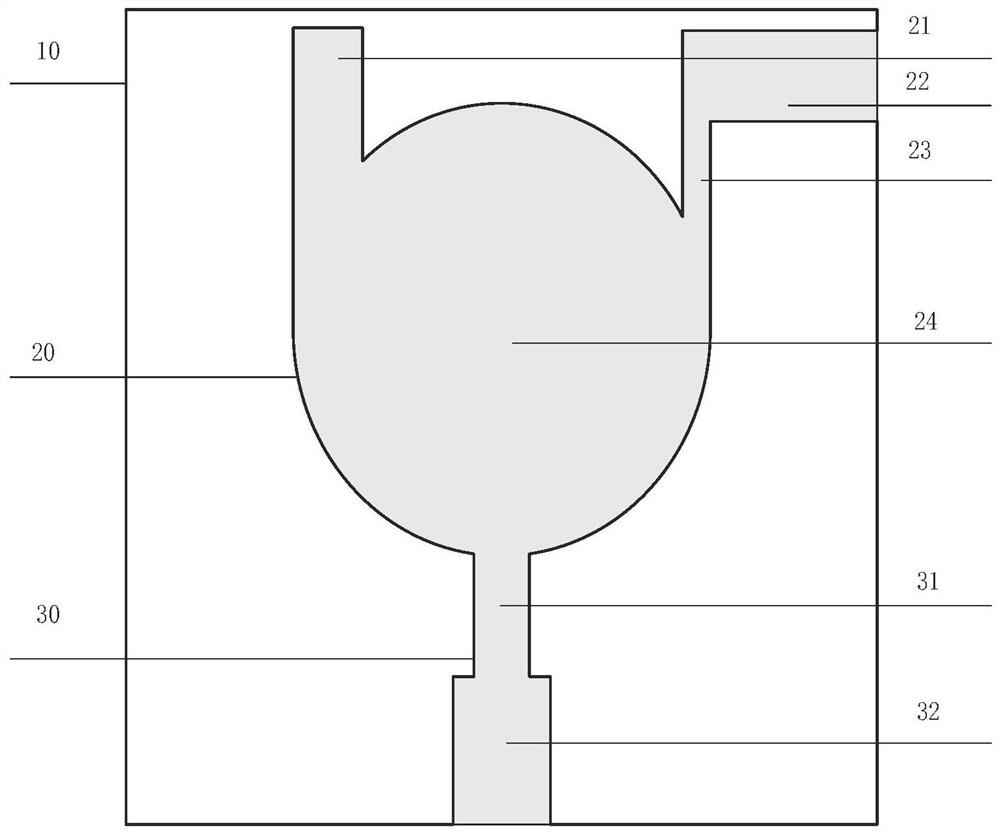
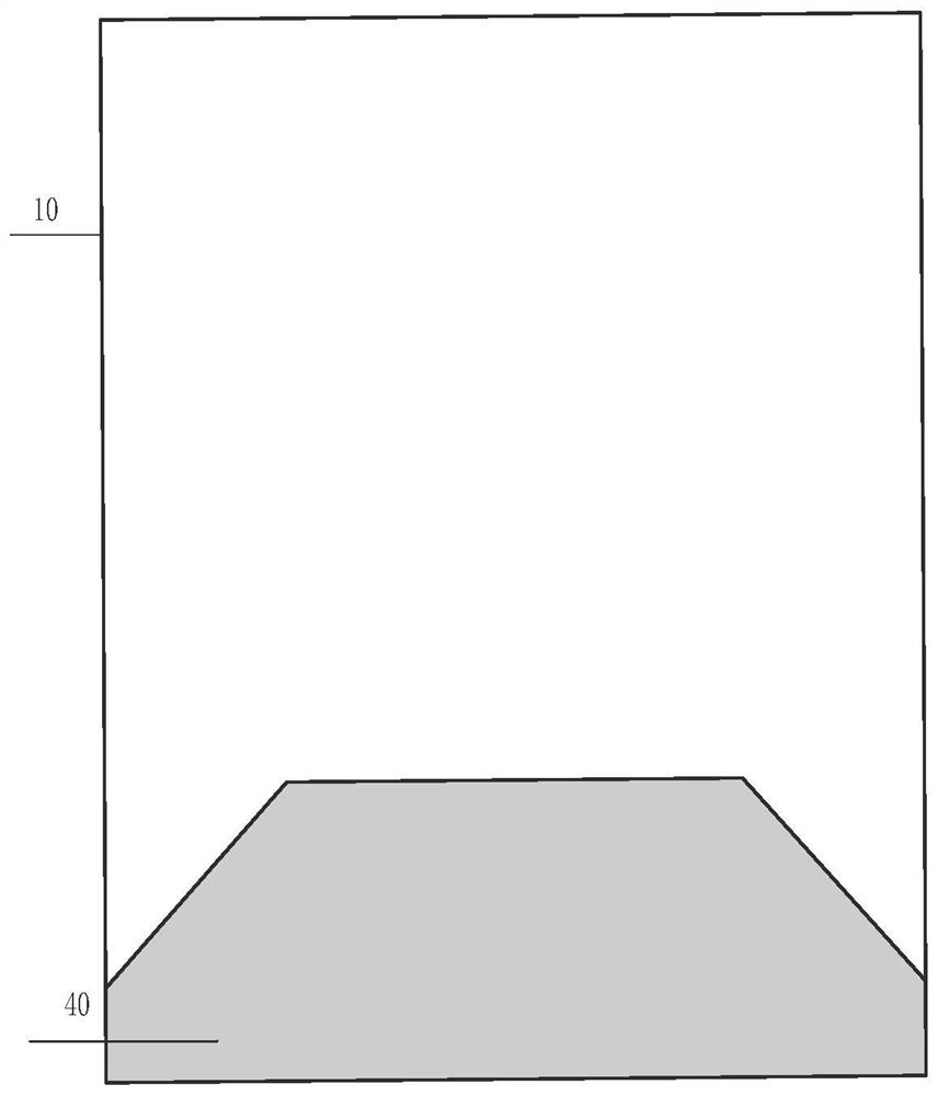
[0034] Such as Figure 1-15 As shown, the miniaturized teapot-shaped UWB antenna of the present invention includes a dielectric substrate 10, a radiation patch 20, a microstrip feeder 30 and a truncated ground plane 40, wherein the radiation patch 20 and the microstrip feeder 30 are printed on the dielectric substrate 10 , the truncated ground plate 40 is printed on the back of the dielectric substrate 10 . Such as figure 1 As shown, the radiation patch 20 adopts a circular patch structure 24, ...


PUM

PropertyMeasurementUnit
Radiusaaaaaaaaaa
Horizontal lengthaaaaaaaaaa
Vertical lengthaaaaaaaaaa

Abstract

The invention discloses a miniaturized teapot-shaped ultra-wideband antenna with a frequency range of 3.0-28.7 GHz. The miniaturized teapot-shaped ultra-wideband antenna comprises a dielectric substrate, a radiation patch, a microstrip feeder line and a truncated grounding plate. The radiation patch adopts a circular structure to load a rectangular branch knot and an L-shaped branch knot structure; and the microstrip feeder line adopts a stepped structure, and the grounding plate adopts a triangular corner cut structure, namely triangular corner cut is performed on the left upper corner and the right upper corner of the grounding plate respectively. According to the invention, the circular structure is adopted to load the rectangular branch knot and the L-shaped branch knot to serve as the radiation patch, the circular structure achieves the basic wideband performance, the rectangular branch knot expands the high-frequency range, the L-shaped branch knot expands the low-frequency range, the three structures are combined together, and the bandwidth of the ultra-wideband antenna is expanded; the micro-strip feeder line adopts the stepped structure and is used for impedance matching; due to a corner cut grounding plate structure, a return loss curve becomes smoother, and radiation is more stable; and the antenna provided by the invention has the advantages of a wide frequency band range, a simple structure, a good radiation characteristic and a high anti-interference capability.

Description

technical field [0001] The invention belongs to the technical field of wireless communication, in particular to a miniaturized teapot-shaped ultra-wideband antenna. Background technique [0002] With the rapid development of data communication technology, low-cost wireless systems have become people's first choice. Since the U.S. Federal Communications Commission (FCC) divided the 3.1-10.6GHz ultra-wideband frequency band into the civil communication field in 2002, ultra-wideband technology has attracted the attention of the academic and commercial circles, especially in short-distance communications. Ultra-wideband (UWB) wireless system is often used in short-distance communication and remote sensing due to its advantages of low power consumption, good security, simple antenna structure, high data transmission rate, simple system design and low cost. Planar antennas, especially monopole antennas, have attracted extensive attention due to their advantages such as wide frequ...

Claims


Application Information

Patent Timeline
IPC IPC(8): H01Q5/25H01Q1/38H01Q1/48H01Q1/50
CPCH01Q1/38H01Q1/48H01Q1/50H01Q5/25
Inventor 南敬昌赵久阳高明明
Owner LIAONING TECHNICAL UNIVERSITY
Learn More