
Gas purification equipment for hydrogen production based on high-temperature fuel waste heat utilization

A technology for gas purification equipment and fuel, which is used in hydrogen/syngas production, liquid contact hydrogen separation, solid contact hydrogen separation, etc., and can solve the problems of poor absorption effect, low carbon dioxide dissolution rate, and insufficient purification. To achieve the effect of improving the removal rate, improving the absorption effect, and improving the purification effect

Active Publication Date: 2021-05-25
HEBEI NORTH UNIV
View PDF6 Cites 0 Cited by
  • Summary
  • Abstract
  • Description
  • Claims
  • Application Information

AI Technical Summary

Problems solved by technology

[0004] In addition to the required hydrogen, the gas coming out of the shift tower also contains carbon dioxide and a small amount of unreacted carbon monoxide, so it needs to be purified. The current method of removing carbon dioxide is to press the gas into water to dissolve CO2, and then pass through the ammonia-containing cuprous formate (or containing cuprous ammonia acetate) solution to remove residual CO to obtain pure hydrogen, but the dissolution rate of carbon dioxide in water is low, the purification is not thorough enough, and after absorbing carbon monoxide with the solution, the concentration of the solution will gradually decrease, and the absorption effect getting worse gradually

Method used


Image

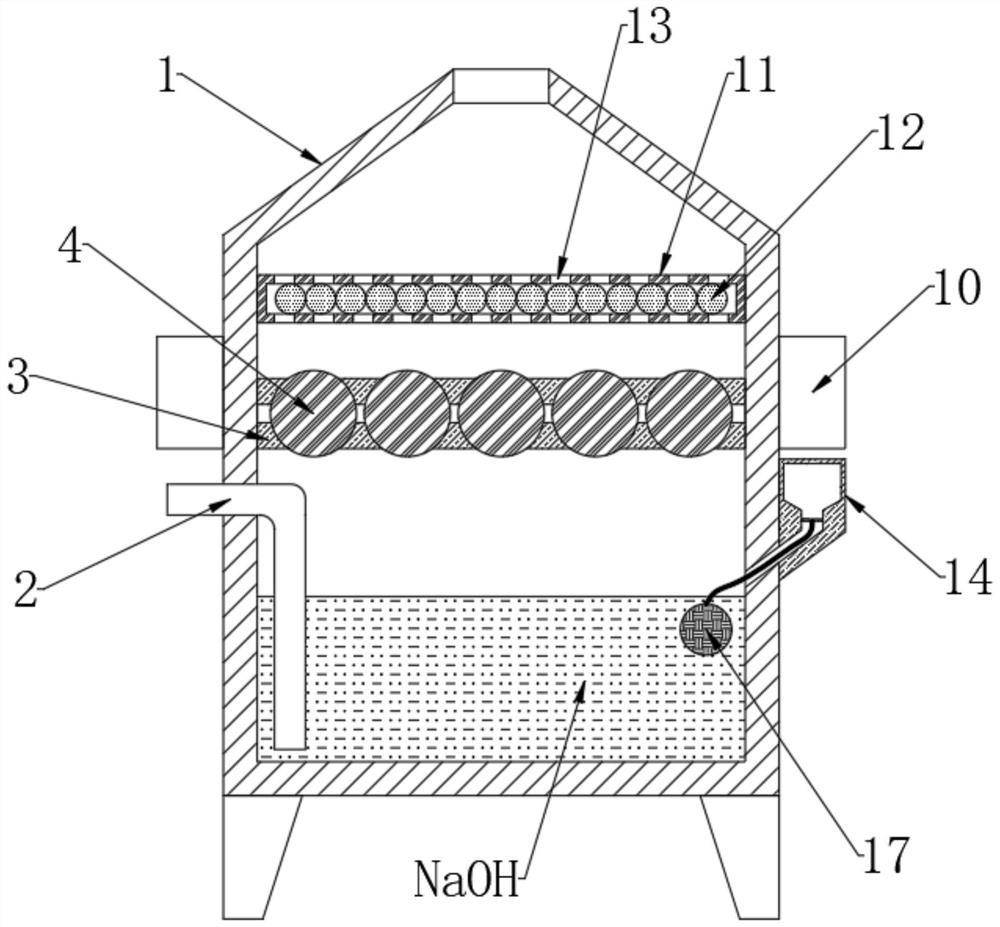
  • Gas purification equipment for hydrogen production based on high-temperature fuel waste heat utilization
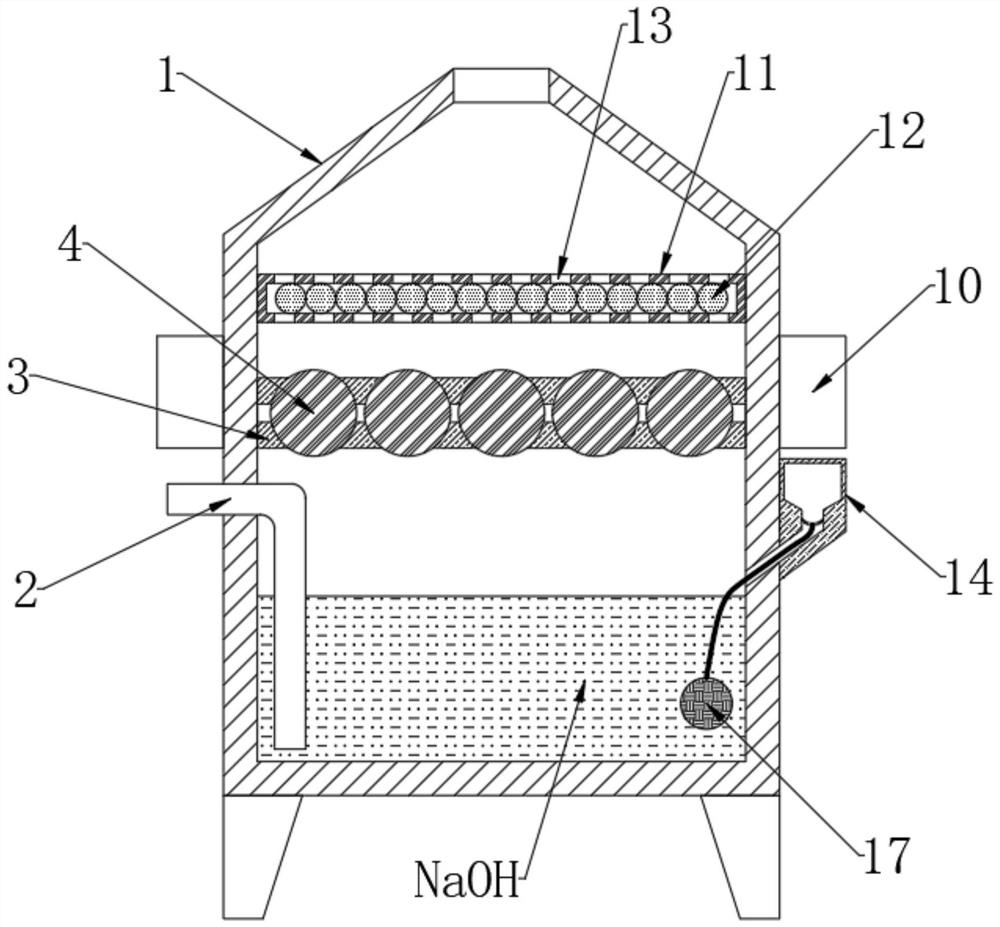
  • Gas purification equipment for hydrogen production based on high-temperature fuel waste heat utilization
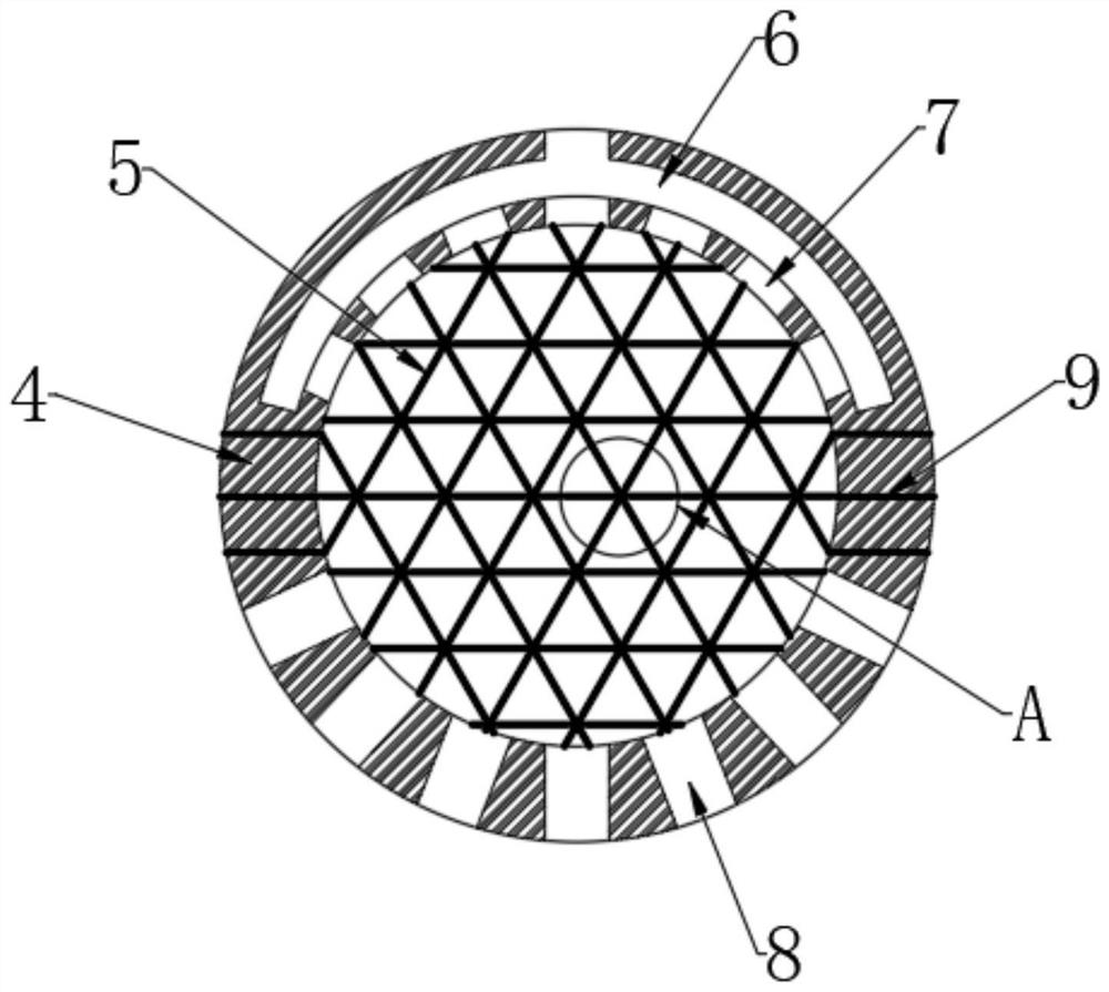
  • Gas purification equipment for hydrogen production based on high-temperature fuel waste heat utilization

Examples


Embodiment

[0044] see Figure 1-7 , a gas purification equipment based on the utilization of high-temperature fuel waste heat to produce hydrogen, please refer to Figure 1-2 , including a purification box 1 with an air outlet on the upper end, and a driving device is provided at the bottom of the purification box 1, in order to allow the sodium hydroxide to fully absorb carbon dioxide, and also to quickly dissolve the newly added sodium hydroxide. The side is connected with an air intake pipe 2, the bottom of the purification box 1 is filled with sodium hydroxide absorption liquid, and the gas outlet end of the air intake pipe 2 is located at the bottom of the sodium hydroxide absorption liquid, and the inner wall of the upper end of the purification box 1 is fixedly connected with a partition plate 3, And a plurality of purification balls 4 are inlaid in the partition plate 3;

[0045] see Figure 3-4 , the inside of the purification ball 4 is provided with a cavity, and the inner wa...


PUM


Abstract

The invention discloses gas purification equipment for hydrogen production based on high-temperature fuel waste heat utilization, which belongs to the field of hydrogen production. The gas purification equipment comprises a purification box with a gas outlet formed in the upper end, one side of the purification box is communicated with a gas inlet pipe, and the bottom of the purification box is filled with sodium hydroxide absorption liquid; and the gas outlet end of thegas inlet pipe is located at the bottom of the sodium hydroxide absorption liquid. According to the scheme, the saturated sodium hydroxide solution is firstly used for absorbing carbon dioxide, and sodium hydroxide can be added into the solution through pulling of the suspension balls in the absorption process, so that the effective concentration of the sodium hydroxide is kept, and the removal rate of the carbon dioxide is effectively increased; the selective adsorption resin on the intercepting net absorbs a hydrochloric acid solution of cuprous chloride from the inside, carbon monoxide penetrating through the intercepting net is absorbed by the selective adsorption resin, and therefore the purpose of purification is achieved, the removal rate of the carbon monoxide is effectively increased, doped water vapor is removed through the water-absorbent resin, and the gas purification effect is further improved.

Description

technical field [0001] The invention relates to the field of hydrogen production, more specifically, to a gas purification device for hydrogen production based on high-temperature fuel waste heat utilization. Background technique [0002] Hydrogen production, the process of producing hydrogen. Hydrogen energy is a secondary energy source. From a long-term perspective, hydrogen production from water is the most promising method. The raw materials are inexhaustible, and water is generated after hydrogen combustion releases energy, which does not cause environmental pollution. Commonly used hydrogen production methods include: hydrogen production from various fossil fuels, hydrogen production from electrolyzed water, hydrogen production from biomass, hydrogen production from other hydrogen-combining substances, and recovery of by-product hydrogen from various chemical processes. Hydrogen production from various fossil fuels is the most important hydrogen production method, but...

Claims


Application Information

Patent Timeline
Patent Type & Authority Applications(China)
IPC IPC(8): C01B3/52C01B3/56
CPCC01B3/52C01B3/56C01B2203/047C01B2203/0475C01B2203/0495Y02P30/00
Inventor 王伟平李俊杰戴彬婷陈晓阳李娜黎国滨
Owner HEBEI NORTH UNIV
Learn More