
Heater impeller and manufacturing method thereof

A heater and impeller technology, applied in heat treatment equipment, metal processing equipment, heat treatment furnace, etc., can solve heat resistance, oxidation resistance and fatigue resistance, unsatisfactory welding performance, unscientific and reasonable structural design, affecting installation and long-term use, etc. Problems, to achieve the effect of reasonable material formula design, conducive to installation and long-term use, and conducive to environmental protection and energy saving

Pending Publication Date: 2021-06-04
XINLI MACHINERY LIYANG CITY
View PDF10 Cites 0 Cited by
  • Summary
  • Abstract
  • Description
  • Claims
  • Application Information

AI Technical Summary

Problems solved by technology

[0004] However, there are deficiencies in the use of the driving impeller of this system. First, the structural design is not scientific and reasonable enough, which is not conducive to uniform air supply to the interior of the compartment; second, Heat resistance, oxidation resistance, fatigue resistance and welding performance are not ideal, affecting installation and long-term use

Method used


Image

  • Heater impeller and manufacturing method thereof
  • Heater impeller and manufacturing method thereof
  • Heater impeller and manufacturing method thereof

Examples


Embodiment 1

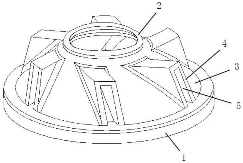
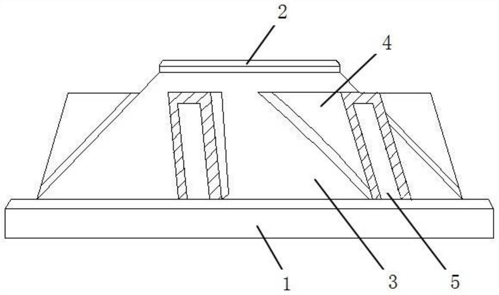
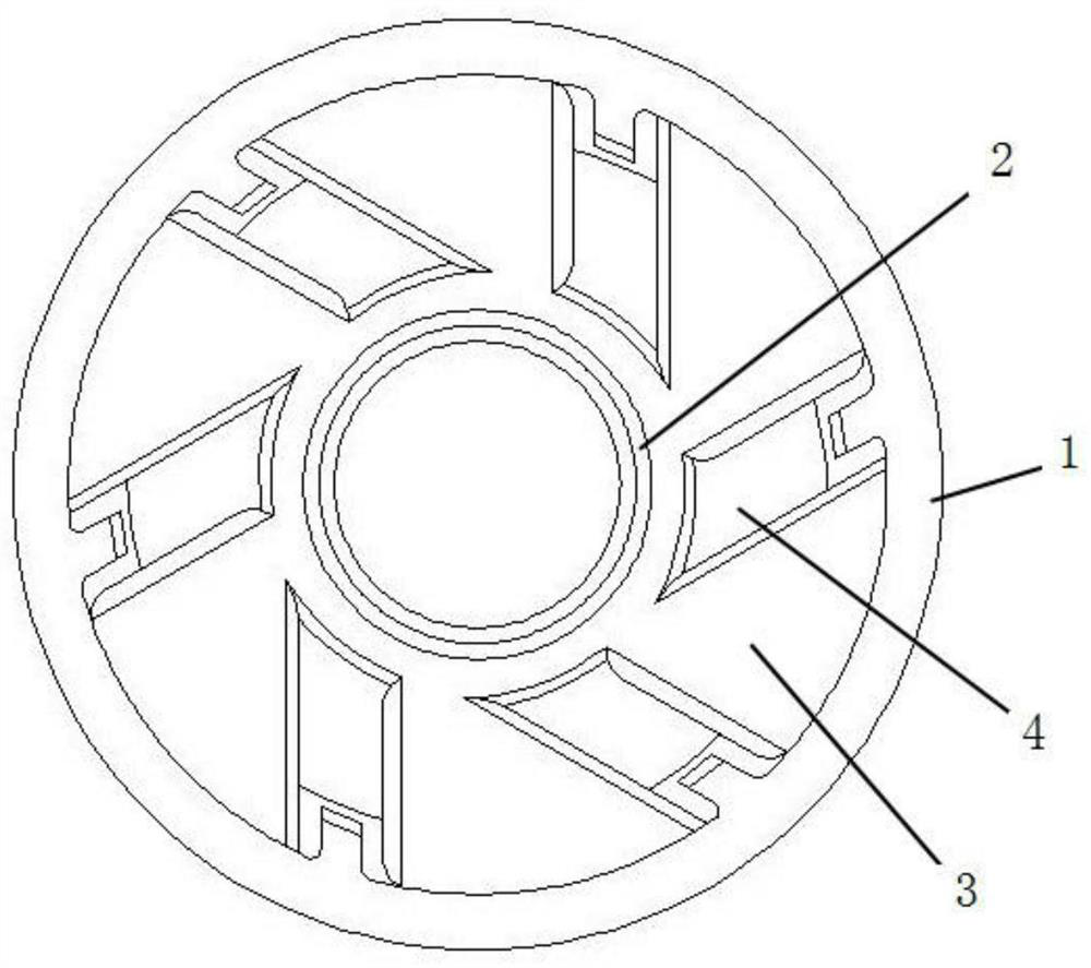
[0033] see Figure 1~3 , in an embodiment of the present invention, a heater impeller includes a first ring portion 1, a second ring portion 2, a cone portion 3 and a blade portion 4, and the cone portion 3 is fixedly installed on the top wall of the first ring portion 1 , and the top of the conical part 3 is fixedly installed with the second ring part 2, wherein the outer diameter of the first ring part 1 is larger than the outer diameter of the second ring part 2, and the wide mouth end of the conical part 3 is sealed with the first ring part 1 connection, the narrow mouth end is sealed with the second ring part 2, and at the same time, the outer surface of the cone part 3 is evenly provided with a number of blade parts 4 along the circumferential direction, and the inside of the blade part 4 is provided with an exhaust channel communicating with the inner area of ​​the cone part 3 5.

[0034] Wherein, the inner sidewall of the second ring part 2 is fixed on the transmissio...

Embodiment 2

[0047] see Figure 1~6 It can be seen that the main structure of this embodiment is the same as that of Embodiment 1, the difference lies in: considering that when the waste heat of the generator is large, the exhaust air speed of the exhaust air channel 5 is limited, which leads to the cooling of part of the waste heat, resulting in the loss of heat Waste, for this reason, we increase the impeller of the heater, increase the exhaust rate of the exhaust channel 5, and further improve the utilization rate of waste heat.

[0048] refer to Figure 4~6 It can be seen that the second ring portion 2 is provided with an annular groove 6 on the bottom wall of the tapered portion 3, and the annular column 7 is fixedly installed in the annular groove 6, and the annular column 7 is away from the outer wall of the second ring portion 2 at the same time. A plurality of fan blades 8 are fixedly installed on the top, and a plurality of partitions 12 parallel to each other are fixedly instal...


PUM

PropertyMeasurementUnit
Outer diameteraaaaaaaaaa

Abstract

The invention discloses a heater impeller and a manufacturing method thereof, and relates to the technical field of impellers. The heater impeller comprises a first ring part, a second ring part, a conical surface part and blade parts. The outer diameter of the first ring part is larger than that of the second ring part. The wider opening end of the conical surface part is connected with the first ring part in a sealed mode. The narrower opening end of the conical surface part is connected with the second ring part in a sealed mode. The blade parts are uniformly arranged on the outer surface of the conical surface part in the circumferential direction, and exhaust channels communicating with the inner side of the conical surface part are formed in the blade parts. The heater impeller is reasonable in structural design, the heater impeller is installed in an air supply pipeline, and the inner diameter of the air supply pipeline is matched with the outer diameter of the first ring part. When a transmission shaft is used for driving the heater impeller to rotate, air heated by the waste heat of an engine can be continuously guided into a compartment, the air is exhausted outwards through the exhaust channels, air outlet is uniform, waste heat utilization of the engine is achieved in the way, and environment protection and energy conservation are facilitated.

Description

technical field [0001] The invention relates to the technical field of impellers, in particular to a heater impeller and a preparation method thereof. Background technique [0002] The engine will generate a lot of heat when it is running, and in the existing naturally aspirated gasoline engine, whether it is a domestic or imported car, only less than 30% of the heat energy is used, about 40% of the heat energy is lost in the exhaust, and about 30% of the heat energy is exhausted. % is lost during engine cooling, which means that up to 70% of available energy is wasted as a result. Due to the high compression ratio of the traditional diesel engine, the engine expansion efficiency is effectively utilized, and its thermal efficiency is only about 37%. At present, the highest thermal energy utilization rate of internal combustion engines in use in the world is only a little over 40%, and a large amount of thermal energy is still wasted in exhaust gas and cooling methods. If a...

Claims


Application Information

Patent Timeline
IPC IPC(8): F01D5/14F01D5/28C22C37/04C22C37/10C22C33/08C21C1/10B22C9/02B22C9/22C21D1/30C21D9/00C21D5/00
CPCF01D5/28F01D5/286F01D5/141F01D5/147C22C37/04C22C37/10C22C33/08C21C1/10B22C9/02B22C9/22C21D1/30C21D9/0068C21D5/00Y02P10/20Y02T10/12
Inventor 陈信华袁贤君
Owner XINLI MACHINERY LIYANG CITY
Learn More