Injection-molded current transformer and preparation method thereof

A current transformer and injection molding technology, which is applied in the direction of current measurement only, voltage/current isolation, and current/voltage measurement, can solve problems such as bubbles in the insulating layer, poor appearance consistency, and reduced withstand voltage strength of the insulating shell. Good insulation and sealing, stable and reliable quality, and good appearance consistency

Pending Publication Date: 2021-06-04
NINGBO ZHONGKE BIPULASI NEW MATERIAL TECH CO LTD
View PDF0 Cites 2 Cited by
  • Summary
  • Abstract
  • Description
  • Claims
  • Application Information

AI Technical Summary

Problems solved by technology

[0004] (1) The insulating shell has a large thickness and poor toughness. If it is improperly handled during pouring and sealing, air bubbles may be generated inside the insulating layer. When the epoxy resin is cured, due to the influence of shrinkage and internal stress, cracks will appear inside the insulating shell, causing Partial discharge reduces the withstand voltage strength of the insulating shell, and even causes the enameled wire to break, which directly affects the protection effect of the coil, and ultimately affects the normal use of the current transformer;
[0005] (2) The current transformer is a combination of two materials, and the appearance is not beautiful. Manual potting is used in the actual potting process. It is difficult to ensure the stability of the potting and sealing, and the filling effect is poor. Human factors have a considerable impact on product quality. As a result, the individual products prepared by the potting process have large differences and poor appearance consistency, which in turn affects the performance consistency of the product

Method used


Image

  • Injection-molded current transformer and preparation method thereof
  • Injection-molded current transformer and preparation method thereof
  • Injection-molded current transformer and preparation method thereof

Examples


Embodiment 1

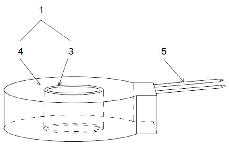
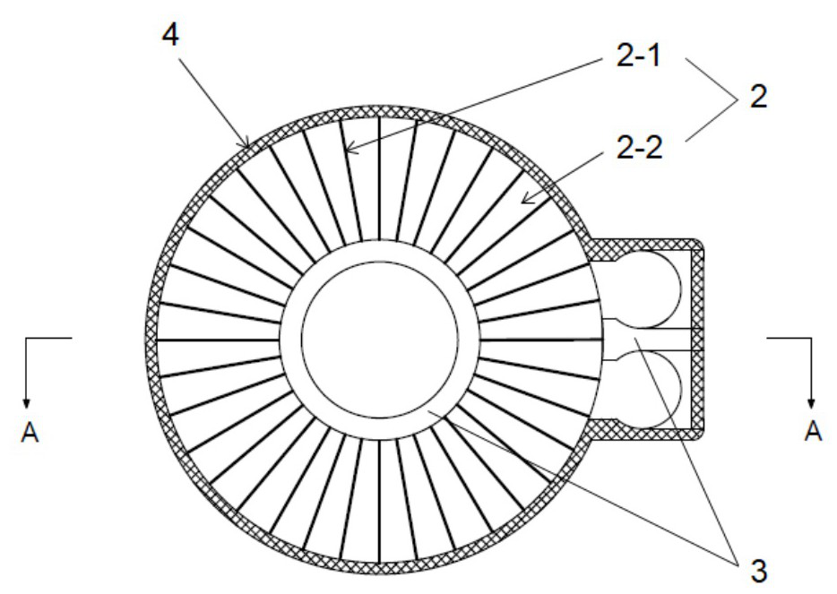
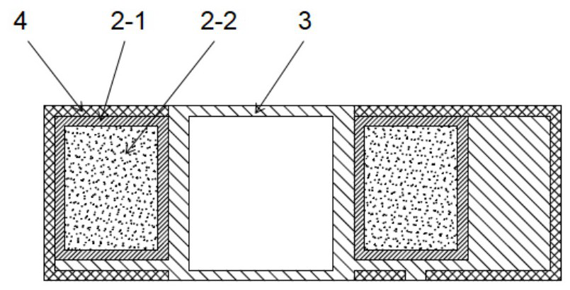
[0035] Such as Figure 1 to 3 In the present invention, the injection molded current transformer is prepared by the injection molding process, including the support body 3 equipped with the winding core 2, including the core 2-2, the enameled wire 2-1, lead 5 and The housing 1, the housing 1 includes a support body 3 and a plastic layer 4 surrounded outside the current transformer. The winding core 2 is wrapped from the lacquer line 2-1 as the secondary winding, and both ends of the enamel wires 2-1 are welded to interfaces of the two leads 5, and the lead 5 is embedded in the lead fixed slot 3-3. The extension of the housing 1 is extended to the housing 1 through the outlet hole 3-4. The material of the core 2-2 can be used in an amorphous soft magnetic alloy, a nanocrystalline mnemy alloy, a ferrite or a slope alloy; the material of the support body 3 can be used in polyethylene terephthalate ( At least one of PBT), polyethylene terephthalate (PET) and styrene-acrylonitrile (AS r...

Embodiment 2

[0044] Such as Figure 6 As shown in the present embodiment, the difference in the injection molded current transformer with the first embodiment is that the boss 3-1 is a cross-shaped convex structure, and four positioning structures are provided on the boss 3-1. The positioning structure is that the positioning the projection 3-1a, the inner hole shape of the winding core 2 matches the outer surface of the boss 3-1. The through hole 3-2 is cross-shaped, and can select the insertion direction of the insertion of the insertion of the bus bar according to the actual needs, and adapt to different application scenarios. Correspondingly, in the preparation method of the injection molded current transformer of the present embodiment, when the support is prepared, the boss 3-1 is the support body injection mold of the cross-shaped column convex structure.

Embodiment 3

[0046] Such as Figure 7 As shown in the present embodiment, the difference in the injection molded current transformer with the first embodiment is that the bosses 3-1 are circular and rectangular bostructures, and two positioning is provided on the boss 3-1. Structure, the positioning structure is a positioning protrusion 3-1B, and the inner hole shape of the winding core 2 matches the outer surface of the boss 3-1. The through holes 3-2 are rounded and rectangular combined structures, which can be used to install a winding wire busbar or pass through the wire directly. Correspondingly, in the preparation method of the injection molded current transformer of the present embodiment, when the support is prepared, the boss 3-1 is used as a support of the boss 3-1 as a circular and rectangular combination of convex structure. Sports injection mold.


PUM

PropertyMeasurementUnit
thicknessaaaaaaaaaa

Abstract

The invention provides an injection-molded current transformer and a preparation method thereof. The current transformer comprises a winding magnetic core, a lead and a shell, the shell comprises a supporting body and a plastic layer surrounding the outer surface of the mutual inductor, the supporting body is composed of a fixing plate, a boss with a through hole, a lead fixing groove and a positioning column, the fixing plate is used for supporting a winding magnetic core, the boss is used for assembling and fixing the winding magnetic core, and the through hole of the boss is used for installing a primary winding; the lead fixing groove and the fixing plate are formed into a whole and are used for fixing the lead; the positioning column is arranged at the bottom of the fixing plate and used for being connected and positioned with an injection mold ejector pin. The winding magnetic core and the supporting body are both arranged in the plastic layer in an injection molding mode. The current transformer is stable and reliable in quality and good in toughness, insulativity and sealing performance, the preparation method of the current transformer comprises the five steps of coil winding, lead connection, supporting body preparation, winding magnetic core assembly and injection molding, the preparation process is simple, and the production efficiency is high.

Description

Technical field [0001] The present invention relates to the technical field of current transformers, and more particularly to a current transformer of injection molding and a preparation method thereof. Background technique [0002] Current transformers are widely used in line current measurements, which can turn large currents into small current electrical equipment for measurement or protection systems. Its main function is to convert high voltage or large current to standard low voltage (100V) or standard small current (5A or 1A, all) to realize standardization, small and small control equipment for measuring instruments, protective equipment and automatic control equipment. . At the same time, transformers can also be used to separate high voltage systems to ensure the safety of personal and equipment. [0003] The existing current transformer is multi-housing, the encapsulation process of the epoxy resin is used, and the cure time of the epoxy resin is about 25 hours, and th...

Claims


Application Information

Patent Timeline
Patent Type & Authority Applications(China)
IPC IPC(8): G01R15/18G01R19/00B29C45/14
CPCB29C45/14B29C45/14221G01R15/183G01R19/0092
Inventor 霍利山白皞郭海门贺王劲马丽黄嘉翔
Owner NINGBO ZHONGKE BIPULASI NEW MATERIAL TECH CO LTD
Why Eureka
Try Eureka