A kind of preparation method and product of directional interconnected high thermal conductivity interface material

An interface material and high thermal conductivity technology, which is applied in the field of preparation of high thermal conductivity interface materials, can solve the problems of unsuitable filling concentration, complex preparation process, difficult processing, etc., so as to improve the strength and thermal stability, the preparation method is simple, and the vertical direction is improved. The effect of thermal conductivity

Active Publication Date: 2022-07-12
武汉华兴志远科技有限公司
View PDF10 Cites 0 Cited by
  • Summary
  • Abstract
  • Description
  • Claims
  • Application Information

AI Technical Summary

Problems solved by technology

[0004] However, the current technologies for preparing composite materials as thermal interface materials all have problems such as complex preparation process, difficult processing and high cost, and are not suitable for filling concentration.

Method used


Image

  • A kind of preparation method and product of directional interconnected high thermal conductivity interface material
  • A kind of preparation method and product of directional interconnected high thermal conductivity interface material
  • A kind of preparation method and product of directional interconnected high thermal conductivity interface material

Examples


preparation example Construction

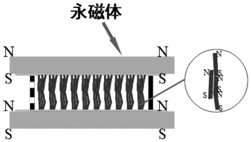
[0026] like figure 1 As shown, a preparation method of the above thermal interface composite material, the preparation method comprises the following steps:

[0027] (1) Preparation of directional interconnected filled particle arrays: The filled particles are placed in a PTFE mold with two small holes on the side, and then the top surface is covered with a glass sheet, on the bottom of the mold and above the glass sheet Place NdFeB permanent magnets with opposite NS poles, and then apply vibration to the mold, so that the filling particles in the mold can be automatically arranged under the action of vibration and magnetic field to form a filling particle array.

[0028] (2) Preparation of thermal interface material: The colloid of the polymer matrix is ​​added to the mold through the two holes on the side of the mold, and the whole device is placed in a vacuum heating box after filling. The mold is repeatedly evacuated 3-5 times for 15 minutes each time. After the air in th...

Embodiment 1

[0044] This embodiment provides a thermal interface composite material, and the specific preparation method includes the following steps:

[0045] (1) Preparation of directional interconnected nickel-plated carbon fiber arrays: 0.1 g of functionalized nickel-plated carbon fiber A (the precursor is PAN-based carbon fiber, with a nickel mass fraction of 80%) is placed on a polymer with two small holes on the side. In the tetrafluoroethylene mold, the top surface is covered with a 2mm thick glass sheet, and a NdFeB permanent magnet with opposite NS poles is placed on the bottom of the mold and above the glass sheet, and the magnetic field strength is 200mT. Then apply vibration to the mold;

[0046] (2) Preparation of thermal interface material: PDMS colloid is added into the mold through the two holes on the side of the mold. After filling, place the entire device in a vacuum oven. Under the normal temperature environment, the mold placed in the vacuum heating box was repeated...

Embodiment 2

[0049] The difference between this example and Example 1 is that in step (1), the nickel-plated carbon fiber A (precursor is PAN-based carbon fiber, nickel mass fraction is 80%) powder is 0.26g, and the magnetic field strength is 300mT.


PUM

PropertyMeasurementUnit
lengthaaaaaaaaaa
lengthaaaaaaaaaa
diameteraaaaaaaaaa

Abstract

The invention belongs to the technical field of polymer composite materials, and discloses a preparation method and product of a directional interconnected high thermal conductivity interface material. The method includes the following steps: S1 adding filler particles into a mold, placing the mold in a permanent magnetic field, and applying vibration to the mold, so that the filler particles are automatically aligned and arranged in the magnetic field under vibration , forming an array of filling particles; S2 maintaining the permanent magnetic field, injecting thermosetting polymer colloid into the mold, and vacuuming the mold to remove the air therein, so that the thermosetting polymer colloid is filled into the filling particle array In the gap, the temperature rises and solidifies, so as to obtain the desired directional interconnected high thermal conductivity interface material. The present application also discloses the product obtained by the above preparation method. The present invention has excellent thermal conductivity, good mechanical strength and processability.

Description

technical field [0001] The invention belongs to the technical field of polymer composite materials, and more particularly, relates to a preparation method and product of a directional interconnected high thermal conductivity interface material. Background technique [0002] With the rapid development of microelectronics technology, electronic devices are becoming more and more miniaturized, and the power density of electrical equipment is increasing. The increase in chip heat generation has led to a continuous increase in the operating temperature of the chip. Excessive chip temperature will affect the stability, reliability and device life of electrical devices. Therefore, chip heat dissipation has become an important factor restricting the performance of electronic devices. The industry generally believes that the bottleneck of the future development of electronic products is not the hardware design but the design of the cooling system. The heat dissipation of the chip ...

Claims


Application Information

Patent Timeline
Patent Type & Authority Patents(China)
IPC IPC(8): B29C39/42B29C39/22B29C39/02B29B13/00C08K3/04C08K3/38C08K7/06C08K9/02
CPCB29C39/003B29C39/02B29C39/42B29C39/22B29B13/00C08K9/02C08K7/06C08K3/041C08K3/38C08K2003/385C08L83/04C08L63/00C08L101/00
Inventor 罗小兵张信峰周姝伶蓝威范义文舒伟程
Owner 武汉华兴志远科技有限公司
Why Eureka
Try Eureka