Continuous forming method and device for deep blind hole shell with pulse current assisted partial upsetting

A pulse current, deep blind hole technology, used in forging/pressing/hammer devices, manufacturing tools, other household appliances, etc. Good plasticity, increasing cumulative deformation, and reducing deformation resistance

Active Publication Date: 2022-07-15
HARBIN INST OF TECH AT WEIHAI
View PDF0 Cites 0 Cited by
  • Summary
  • Abstract
  • Description
  • Claims
  • Application Information

AI Technical Summary

Problems solved by technology

First, the tube blank and blind hole parts are hot-extruded respectively, and then welded and assembled into a deep blind hole structure. However, there is a difference in strength between the weld and the substrate, and the residual stress is large, which is prone to defects such as deformation, pores, slag inclusions, and cracks.
[0005] (3) Multi-pass local loading forming. First, hot extrusion forms a blind hole billet with an inner hole depth-to-diameter ratio ≤ 3, and then multi-pass drawing realizes the overall forming of the deep blind hole shell, but it is difficult to form a positive integrated manufacturing : First, when the number of drawing passes is small and the amount of single deformation is large, the shear deformation is serious, and defects such as cracking and breaking are prone to occur; Third, the accumulated deformation in the multi-pass forming process is determined by the wall thickness change rate of the extruded preform and the final forging billet, and the deformation is fixed and limited. After repeated heating, the consumption is serious, and methods such as multi-pass radial forging also have these types of problems
It can be seen that the existing technology cannot meet the overall forming and manufacturing requirements of high-strength deep blind hole shells, and there is an urgent need to develop new deep blind hole shell forming manufacturing theories and methods

Method used


Image

  • Continuous forming method and device for deep blind hole shell with pulse current assisted partial upsetting
  • Continuous forming method and device for deep blind hole shell with pulse current assisted partial upsetting
  • Continuous forming method and device for deep blind hole shell with pulse current assisted partial upsetting

Examples


specific Embodiment approach 1

[0109] step one:

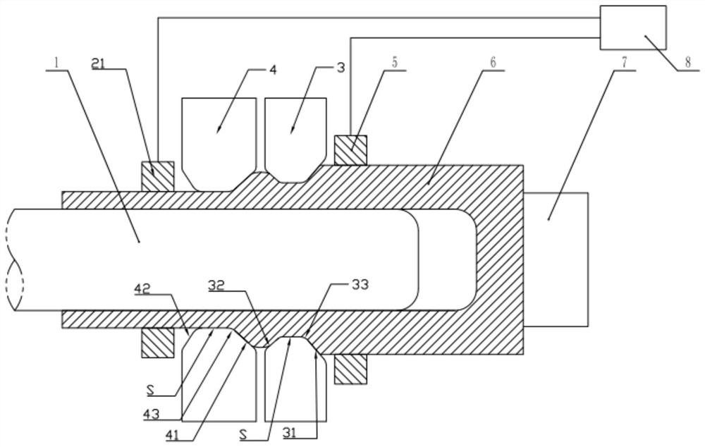
[0110] Select AerMet100 ultra-high-strength steel (23Co14Ni12Cr3MoE) cylindrical preform 6 with an outer diameter of 28mm and a height of 40mm, and prepare blind hole parts with an outer diameter of 28mm, an inner diameter of 12mm, a length of 46mm, and a hole depth of 30mm by hot extrusion forming equipment as preform 6 .

[0111] Step 2:

[0112] The axial thickness of the first group of hammer heads 3 is 14mm, the inclination of the first inlet flared conical surface 31 is 20°, the length of the radial loading working surface S is 4mm, the radius of the first transition fillet 33 is 20mm, and the first outlet flare The inclination of the mouth cone surface 32 is 60°; the overall thickness of the second group of hammer heads 4 is 14mm, the inclination of the second inlet flaring cone surface 41 is 60°, the length of the radial loading working surface S is 5mm, and the second transition fillet is 43 has a radius of 5mm. The radial depression amount of th...

specific Embodiment approach 2

[0125] step one:

[0126] Choose 30CrMnSiNi with an outer diameter of 26mm and a height of 40mm 2 A cylindrical preform 6, a blind hole with an outer diameter of 26 mm, an inner diameter of 12 mm, a length of 44 mm, and a hole depth of 28 mm is prepared as a preform 6 by hot extrusion forming equipment.

[0127] Step 2:

[0128] The axial thickness of the first group of hammer heads 3 is 14mm, the inclination of the first inlet flared conical surface 31 is 18°, the length of the radially loaded working surface S is 4mm, the radius of the first transition fillet 33 is 20mm, and the first outlet flare The inclination of the mouth cone surface 32 is 60°; the overall thickness of the second group of hammer heads 4 is 14mm, the inclination of the second inlet flaring cone surface 41 is 60°, the length of the radial loading working surface S is 5mm, and the second transition fillet is 43 has a radius of 5mm. The radial depression amount of the first group of hammer heads 3 is sel...

specific Embodiment approach 3

[0141] step one:

[0142] A 7075 aluminum alloy cylindrical preform 6 with an outer diameter of 24 mm and a height of 40 mm is selected, and a blind hole with an outer diameter of 24 mm, an inner diameter of 12 mm, a length of 46 mm, and a hole depth of 30 mm is prepared by hot extrusion forming equipment as the preform 6. .

[0143] Step 2:

[0144] The axial thickness of the first group of hammer heads 3 is 14mm, the inclination of the first inlet flared conical surface 31 is 16°, the length of the radial loading working surface S is 4mm, the radius of the first transition fillet 33 is 20mm, and the first outlet flare The inclination of the mouth cone surface 32 is 60°, and the radius of the first transition fillet 33 with the radial loading working surface S is 1.5mm; the overall thickness of the second group of hammer heads 4 is 14mm, and the second inlet flared cone surface 41 is inclined The angle is 60°, the length of the radially loaded working surface S is 5mm, and ...


PUM

PropertyMeasurementUnit
thicknessaaaaaaaaaa
thicknessaaaaaaaaaa

Abstract

The invention discloses a continuous forming method and device for deep blind hole shells with pulse current assisted partial upsetting. Blind hole parts formed by hot extrusion are used as preforms, and local high-frequency pulse upsetting is applied to the wall preforms through two sets of rotary forging hammers with progressive radial positions. "Forging" means that the hammer head is loaded in the radial direction of the component, and the deformation zone acted by a single set of hammer heads can be regarded as axial elongation. Deformation towards upsetting; the deformation zone of the preform is a severe plastic deformation of the combination of "drawing-upsetting-drawing", which can effectively increase the accumulated deformation, refine the microstructure of components, and improve the radial compression in the single-pass forming process / Axial extension efficiency; at the same time, a large pulse current is applied online to the upsetting deformation area of ​​the preform, and the electroplastic effect is used to reduce the deformation resistance of the material and improve the formability. Good, it is good for thin wall forming.

Description

technical field [0001] The invention relates to a device and a method in the technical field of material processing, in particular to a continuous forming device for deep blind hole shell pulse current assisted partial upsetting. Background technique [0002] At present, the mainstream manufacturing methods of ultra-high-strength steel deep blind hole shells at home and abroad mainly include: [0003] (1) Forging blank cutting. First, multi-pass upsetting is used to manufacture forged bars, and then the deep blind hole structure is directly machined, which has long manufacturing cycle (usually more than 3 days), low material utilization rate (utilization rate lower than 30%), and poor strength and toughness of components. and other problems; and there are knife marks in the inner hole; [0004] (2) Segmental plastic forming + welding. First, the tube blank and the blind hole are formed by hot extrusion, and then welded and assembled into a deep blind hole structure. Howev...

Claims


Application Information

Patent Timeline
Patent Type & Authority Patents(China)
IPC IPC(8): B21J5/06B21J7/16B21K21/00
CPCB21J5/06B21J7/16B21K21/00
Inventor 陈刚常旭升姜孟豪王卫卫陈强
Owner HARBIN INST OF TECH AT WEIHAI
Why Eureka
Try Eureka