Power bogie based on novel motor suspension structure and upper swing bolster

A power bogie and frame technology, applied in the direction of the bogie, the transmission device driven by the motor, the device for lateral relative movement between the bottom frame and the bogie, etc. system problems

Pending Publication Date: 2021-06-25
CRRC CHANGCHUN RAILWAY VEHICLES CO LTD
View PDF2 Cites 0 Cited by
  • Summary
  • Abstract
  • Description
  • Claims
  • Application Information

AI Technical Summary

Problems solved by technology

However, this installation method relies on the frame g and is completely rigidly connected with the motor hanger t and the gear box hanger u. The layout position and welding process of the motor hanger t and the gear box hanger u are not only important Higher requirements are put forward for the structural strength and symmetry accuracy of the bogie, and it also increases the overall structural size and radius of gyration of the bogie, which is not conducive to the improvement of its minimum curve passing capacity, and because the lifting lug of the r casing of the traction motor is not removable The rigid structure causes it to interfere with the structure of the frame and the gear box and prevents the traction motor r from being removed directly from the bottom of the car body through the maintenance ditch. Instead, a crane must be used to separate the car body above the frame from the frame. Removing the traction motor r from above the frame greatly increases the difficulty of motor maintenance and replacement
At the same time, the rigid connection of the motor hanger t and the gearbox hanger u also leads to the lack of sufficient vibration reduction protection system for the traction motor r and the gearbox s, which in turn makes the auxiliary structures such as the anti-snake shock absorber and the anti-rolling torsion bar n Installation becomes an indispensable and necessary supplement
[0006] In addition, different train design speed requirements or different side beam structures will also have a great impact on the layout space and structural form of the secondary suspension device, motor and gearbox, often resulting in the layout of the old secondary suspension device. The scheme cannot meet the requirements of the installation location and vibration reduction index, so the old reference scheme must be overthrown, and a design improvement with a new concept must be made
[0007] like Figure 5 to Figure 7 As shown, the existing large gear s-2 installed inside the shell s-1 of the snap-fit ​​and spliced ​​gearbox is directly press-fitted with the bearing outer ring s-3-2 on the large gear bearing s-3 to form a coaxial fixed connection Interference fit, the gear box installation shaft section d-1 on the axle d is directly press-fitted with the large gear bearing inner ring s-3-1 on the large gear bearing s-3 to form a coaxial fixed interference fit, the process The coaxial fixed connection form of the interference fit makes the gearbox installation shaft section d-1, the gearbox bearing s-3 and the large gear s-2 become an inseparable whole, and, due to the snap-fit ​​spliced ​​gearbox shell s- 1 has low structural strength, and it cannot be directly used as the focus point of the withdrawal baffle on the wheel shaft withdrawal press. Moreover, the bearing inner ring of the existing large gear bearing s-3 is too narrow, resulting in that even if the wheel shaft withdrawal pressure The on-board unloading baffle is refitted into a multi-jaw chuck and inserted into the gear box through the axle through hole on the axial side wall of the gear box. However, due to the lack of sufficient radial force points, it is still impossible to reliably clamp the large The inner ring s-3-1 of the gear bearing implements the radial withdrawal blocking force, so that the withdrawal of the axle cannot be directly implemented, and then when the subsequent maintenance of the axle d or the large gear s-2 must be buckled and spliced The gearbox casing s-1 is the first to release the original splicing and fastening state, and the axle d, the large gear s-2 and the large gear bearing s-3 that are coaxially fixed with it are removed from the frame as a whole. Then transfer to the axle unloading press to complete the unloading and replacement operation
The process of this method is cumbersome, time-consuming and labor-intensive, and it is impossible to remove and replace the axle d independently without removing the large gear s-2 from the snap-fit ​​spliced ​​gearbox casing s-1, and it is also impossible to maintain the buckle. Under the premise that the shell s-1 of the spliced ​​gearbox is in the fastened state, pull out the axle d separately and directly repair the large gear s-2 in the shell s-1 of the gearbox from the hole left after the axle d is removed. and lubrication maintenance

Method used


Image

  • Power bogie based on novel motor suspension structure and upper swing bolster
  • Power bogie based on novel motor suspension structure and upper swing bolster
  • Power bogie based on novel motor suspension structure and upper swing bolster

Examples


Embodiment Construction

[0055] The present invention will be described in further detail below in conjunction with the accompanying drawings.

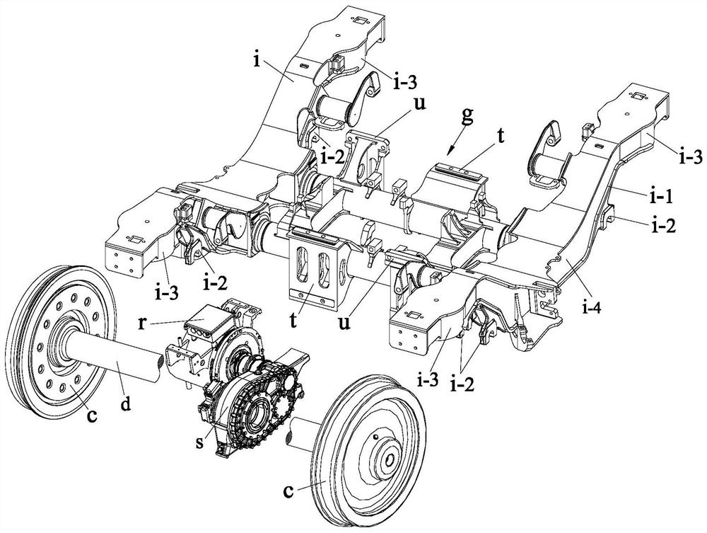
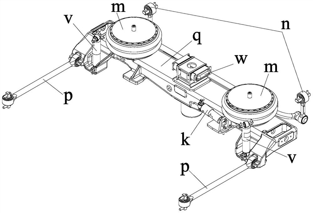
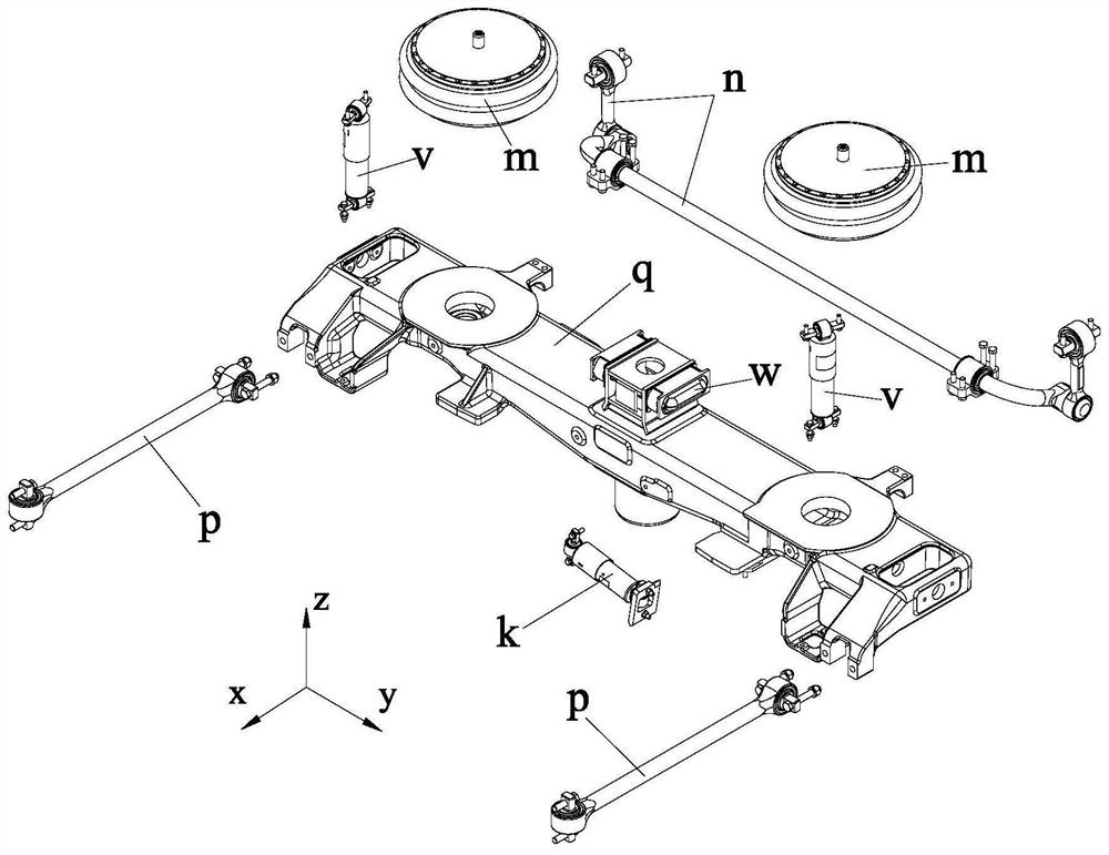
[0056] like Figure 8 to Figure 19 As shown, the present invention is based on a new motor suspension structure and a power bogie with an upper bolster, which includes a frame, a wheel set device composed of wheels and axles, and the frame includes two frame side beams 1-1 and two frame beams 1 -2. The frame side beam 1-1 includes a side beam middle section 1-1-1 at a lower position as the connecting part of two bird wings and two bird wing-shaped wings symmetrically fixed to both ends of the side beam middle section 1-1-1. The cantilever section 1-1-2 of the side beam, the cantilever section 1-1-2 of the bird wing-shaped side beam is formed by connecting an upward tilted section and a horizontal extension section extending horizontally outward;

[0057] It is characterized in that the bogie also includes an easy-to-retract shaft gearbox, a side beam single-...


PUM


Abstract

The invention discloses a power bogie based on a novel motor suspension structure and an upper swing bolster, and belongs to the field of railway vehicle power bogie devices. The power bogie comprises a framework, a wheel set device composed of wheels and axles, an easy-to-withdraw shaft type gearbox, a side beam single-point suspension type motor, the integrated vibration reduction type swing bolster and a secondary suspension system. On the premise that the mounting position and the vibration reduction index of the primary suspension axle box device are ensured, the transverse width size and the turning radius of the whole bogie are effectively reduced, the curve passing capacity of the bogie is further improved, and the annular vibration reduction axle box is convenient to mount, dismount and maintain; and after four fastening bolts are respectively dismounted, the side beam single-point suspension type motor can be directly and independently dismounted from the lower part of the vehicle body through the maintenance trench.

Description

technical field [0001] The invention belongs to the field of rail vehicle power bogie devices, in particular to a power bogie based on a novel motor suspension structure and an upper bolster. Background technique [0002] The design of rail train bogies not only needs to comprehensively consider the structural strength of the main body of the load-bearing frame, the effect of various auxiliary damping components such as anti-snake dampers, and the installation method of the braking mechanism, but also needs to be aimed at different According to the train’s theoretical speed, bearing load, minimum curve curvature, snow and flying stones and other road conditions, comprehensively design the suspension mode of the power bogie motor, the layout space of the motor and its gearbox, the primary suspension and the secondary suspension. There are many factors such as the structural form and layout space of the suspension device. Various design schemes developed around the above-ment...

Claims


Application Information

Patent Timeline
Patent Type & Authority Applications(China)
IPC IPC(8): B61F5/52B61C9/50B61F15/20B61F5/10B61F5/12
CPCB61C9/50B61F5/10B61F5/12B61F5/52B61F15/20
Inventor 刘海涛赵克楠李晓峰刘志远
Owner CRRC CHANGCHUN RAILWAY VEHICLES CO LTD
Why Eureka
Try Eureka