Biomass fuel mild pyrolysis device and process

A technology of biomass fuel and pyrolysis, which is applied in the fields of biofuel, petroleum industry, special form of dry distillation, etc. It can solve the problems of difficult contact, increased heat loss of exhaust smoke, complex equipment structure, etc., and achieve mass yield and energy production High efficiency, reduced heat loss, and improved collection efficiency

Active Publication Date: 2021-06-25
SHANGHAI ELECTROMECHANICAL DESIGN & RES INST CO LTD
View PDF12 Cites 0 Cited by
  • Summary
  • Abstract
  • Description
  • Claims
  • Application Information

AI Technical Summary

Problems solved by technology

The main problems in the direct combustion process of biomass fuel are as follows: 1. The water content of the raw material is high, and it takes a long time to dry and preheat at a higher temperature. The furnace and the evaporating heating surface corrode greatly; 2. The light volatile content is high, but its calorific value is relatively low, resulting in a low temperature field in the furnace after combustion, making it difficult to ensure stable combustion; 3. Light volatile combustion After exhaustion, the ashes surround the coke particles, and it is difficult for the air to contact with the coke particles, resulting in slow burning speed and difficulty in burning out.
Chinese patent 201480074767.7 discloses a torrefaction reactor transformed from a standard commercial vibrating dryer. The equipment has a complex structure and is difficult to miniaturize, and is more suitable for scenarios where biomass fuel raw materials are relatively concentrated
The existing traditional manual collection of loose rods or the use of balers to pick up and bundle them in the field and send them to the storage point not only has high costs and low operating efficiency, but also the high moisture content of biomass fuel raw materials can easily cause raw materials to rot and deteriorate.

Method used


Image

  • Biomass fuel mild pyrolysis device and process
  • Biomass fuel mild pyrolysis device and process

Examples


Embodiment Construction

[0026] The present invention will be further described below in conjunction with the accompanying drawings and specific embodiments.

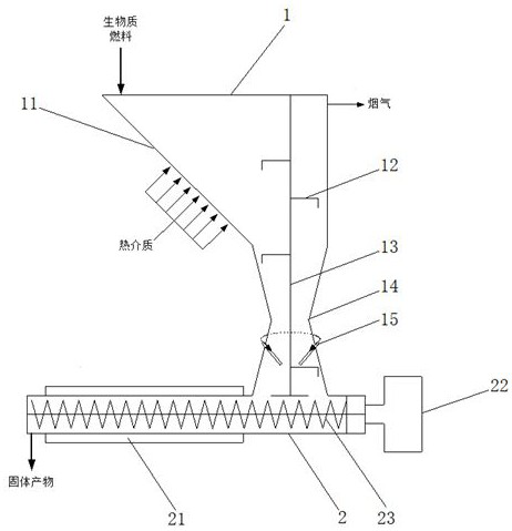
[0027] see figure 1 , a kind of biomass fuel mild pyrolysis device, comprising a housing 1 and a screw discharger 2; the upper end of the housing 1 is provided with a feed inlet, and the inner cavity of the housing 1 is sequentially provided with a drying area, a reaction area and a Unloading area.

[0028] An inclined surface 11 is arranged on one side of the drying area, the upper end of the inclined surface 11 is located below the material inlet, the lower end of the inclined surface 11 is connected to the reaction area, and several air inlet holes are arranged on the inclined surface 11. A gas outlet is provided on the shell 1 on the other side of the drying zone, and a stirring part is provided on the other side of the drying zone, and the stirring part extends downwards through the reaction zone and the feeding zone in sequence. The sti...


PUM


Abstract

The invention relates to a biomass fuel mild pyrolysis device and process. The device comprises a shell (1) and a spiral discharging machine (2), A feeding hole is formed in the upper end of the shell, and a drying area, a reaction area and a blanking area are sequentially arranged in an inner cavity of the shell from top to bottom; A slope (11) is arranged on one side of the drying area, the upper end of the slope is located below the feeding port, and the lower end of the slope is connected with the reaction area; A gas outlet is formed in the shell on the other side of the drying area, a stirring part is arranged on the other side of the drying area, and the stirring part extends downwards to sequentially pass through the reaction area and the blanking area; A nozzle (15) is arranged on the shell of the reaction area and is used for introducing air flow for combustion; The lower end of the discharging area is connected with an inlet of the spiral discharging machine. And a heat exchanger (21) is arranged on the outer wall of the spiral discharging machine. Integrated drying, mild pyrolysis and cooling treatment of biomass fuel can be achieved, the characteristics of the fuel are improved, and automatic operation and mobile operation of biomass fuel processing treatment can be achieved easily.

Description

technical field [0001] The invention relates to biomass fuel thermal pretreatment technology, in particular to a biomass fuel gentle pyrolysis device and process. Background technique [0002] Biomass fuels generally use biomass resources such as crop stalks, agricultural product processing by-products and waste (agricultural processing residues), forestry waste (forestry processing residues) and energy crops as raw materials. Due to factors such as large seasonal fluctuations and unstable supply of straw raw materials, some biomass power plants usually consider blending coal to ensure that the generating units can provide stable power. [0003] At present, biomass direct combustion power generation is widely used, that is, direct combustion of biomass fuel for power generation. The direct combustion process mainly includes preheating and drying (moisture removal), light volatiles (CH 4 , CO, CO 2 etc.) precipitation and combustion of residual coke particles (fixed carbon...

Claims


Application Information

Patent Timeline
Patent Type & Authority Applications(China)
IPC IPC(8): C10B53/02C10B57/00
CPCC10B53/02C10B57/00Y02E50/10
Inventor 王小泉席玉明刘传江斯信忠莫龙庭徐良
Owner SHANGHAI ELECTROMECHANICAL DESIGN & RES INST CO LTD
Why Eureka
Try Eureka