Tubular high-pressure micro-dispersion mixer

A micro-dispersion and mixer technology, applied in fluid mixers, mixers, chemical instruments and methods, etc., can solve problems such as limited applications, and achieve a continuous effect in the mixing process

Inactive Publication Date: 2021-06-29
TSINGHUA UNIV
View PDF9 Cites 2 Cited by
  • Summary
  • Abstract
  • Description
  • Claims
  • Application Information

AI Technical Summary

Problems solved by technology

Although this type of equipment has achieved good results in practical applications, the sealing of these micro-dispersion mixing equipment still uses laminated sheets, thus limiting its further application in high-pressure systems

Method used


Image

  • Tubular high-pressure micro-dispersion mixer
  • Tubular high-pressure micro-dispersion mixer
  • Tubular high-pressure micro-dispersion mixer

Examples


Embodiment 1

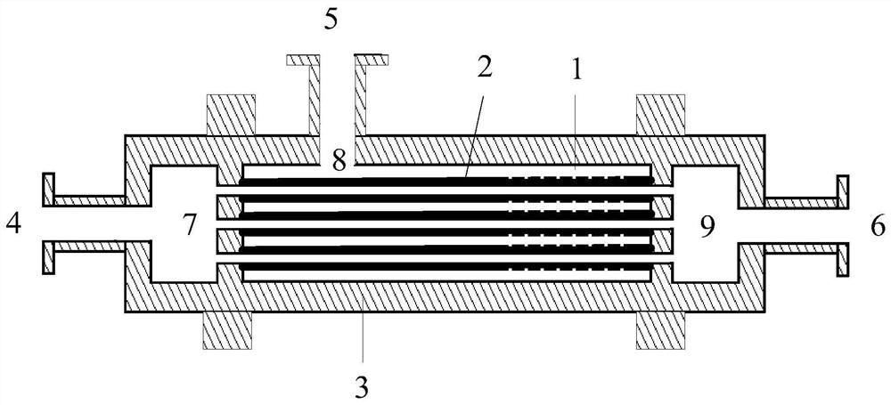
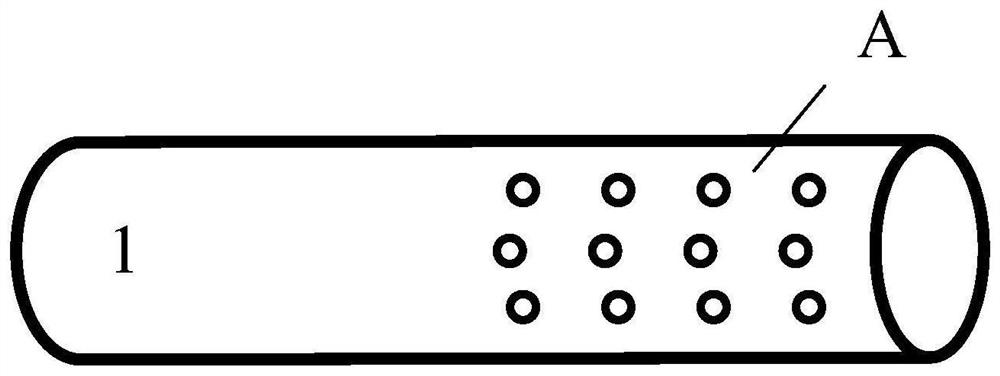
[0044] Pure water is used as the main fluid, and an aqueous solution containing 0.1wt.% fluorescein sodium is used as the fluid to be dispersed. The two fluids are homogeneously mixed by a micro-mixer containing 20 tubes. The inner tube length of the mixer is 30cm, the inner diameter is 2mm, the outer diameter is 3mm, the minimum distance between the tubes is 12mm, and the material is 316L stainless steel. 36 micro-sieve holes with a diameter of 0.5 mm are evenly arranged in a triangular arrangement at a position between 15-30 cm from the tube inlet. The diameter of the pressure-bearing shell outside the tube is 80mm, and the material is 316L stainless steel. Both ends of the casing are arranged with a cylindrical feed distribution chamber and a discharge collection chamber with a length of 40 mm, and the distance between the central line of the inlet pipe of the dispersed fluid and the inlet position of the array pipe is 6 cm. During operation, the flow rate of the main flui...

Embodiment 2

[0046] An aqueous solution of 1 wt.% sodium lauryl sulfate is used as the main fluid, n-hexane is used as the fluid to be dispersed, and the two fluids are mixed heterogeneously by the micro-mixer described in Example 1. During operation, the flow rate of the main fluid is 7.5L / min, the flow rate of the fluid to be dispersed is 1L / min, and the back pressure at the outlet of the mixer is 10MPa (operating pressure). The test results show that n-hexane at the outlet of the mixer is uniformly distributed in the aqueous solution of sodium lauryl sulfate, the average droplet diameter is 32 μm, and the relative deviation of droplet diameter distribution is 26%.

Embodiment 3

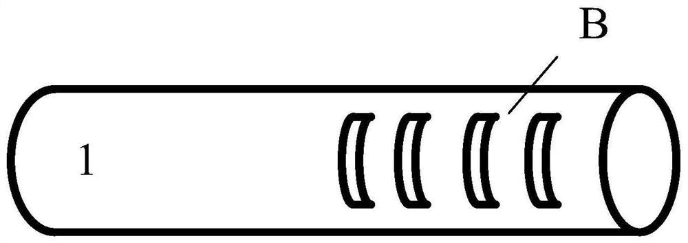
[0048] The aqueous solution of polyvinyl alcohol (viscosity about 560mPa·s) is used as the main fluid, and the aqueous solution of 3wt.% HCl is used as the fluid to be dispersed. The two fluids are homogeneously mixed through a micro-mixer containing a single micro-mesh dispersing tube. The mixer has an inner tube length of 50 cm, an inner diameter of 10 mm, and an outer diameter of 12 mm, and is made of silicon carbide ceramics. Four micro-sieve holes with a diameter of 2mm are evenly arranged along the circumferential direction of the pipeline at a distance of 25cm from the entrance of the tube array. The diameter of the pressure-bearing shell outside the tubes is 30mm, and the material is carbon steel lined with F40 fluoroplastic. Both ends of the casing are arranged with a cylindrical feed distribution chamber and a discharge collection chamber with a length of 90mm, and the distance between the central line of the inlet pipe of the dispersed fluid and the inlet position o...


PUM


Abstract

The invention discloses a tubular high-pressure micro-dispersion mixer and belongs to the technical field of chemistry and chemical engineering. The micro-dispersion mixer adopts a tube array layout, the shell of the mixer is used for bearing high pressure, micro sieve pores or micro grooves positioned at the downstream of a tube array are used as a dispersion structure, and a cavity between the tube array and the shell is used as a fluid distribution chamber. In the operation process, a specific dispersion structure can be selected according to the physical property of the system, the macromixing of a homogeneous system or the dispersion of liquid drops and bubbles of a heterogeneous system can be completed in the mixer only by respectively introducing the fluid to be dispersed and the main fluid, and the mixing process is continuous, efficient and stable.

Description

technical field [0001] The invention relates to the technical field of chemistry and chemical engineering, in particular to a tube-and-tube high-pressure micro-dispersion mixer. Background technique [0002] In chemical production, high-pressure systems are often used to strengthen chemical reaction and separation processes, such as supercritical carbon dioxide extraction, high-pressure synthesis of 2-mercaptobenzothiazole, high-pressure carbonylation of high-carbon organic acids, etc. In high-pressure chemical equipment, because it is difficult to implement efficient stirring operations, passive mixing is more suitable for high-pressure chemical processes, especially for the continuous high-pressure chemical process. [0003] In recent years, the development of micro-chemical technology has provided new ideas for the rapid mixing of high-pressure chemical systems, especially the small equipment volume of micro-mixing equipment is very easy to manufacture as high-pressure eq...

Claims


Application Information

Patent Timeline
Patent Type & Authority Applications(China)
IPC IPC(8): B01F13/10B01F13/00B01F13/06B01F5/06
CPCB01F25/4323B01F25/4521B01F33/30B01F33/71B01F33/82
Inventor 王凯骆广生
Owner TSINGHUA UNIV
Why Eureka
Try Eureka