High-temperature adjacent metal heat treatment device and method

A technology for metal heat treatment and heat treatment equipment, which is applied in heat treatment equipment, heat treatment process control, manufacturing tools, etc., and can solve problems such as high power consumption, unsuitable for wide application, and inability to achieve batch processing.

Pending Publication Date: 2021-07-30
HUAZHONG UNIV OF SCI & TECH
View PDF15 Cites 3 Cited by
  • Summary
  • Abstract
  • Description
  • Claims
  • Application Information

AI Technical Summary

Problems solved by technology

However, high-frequency induction heating and current heating have requirements on the nature and shape of the material to be processed, and both require special fixtures. Laser heating consumes a lot of energy and is not suitable for wide application.
These technologies can realize rapid heating treatment of a single workpiece, but none of them have batch processing capabilities.
The invention patent with the publication number CN112094995A heats the metal material by directly electrifying the metal material, but the excellent electrical conductivity of the me

Method used


Image

  • High-temperature adjacent metal heat treatment device and method
  • High-temperature adjacent metal heat treatment device and method
  • High-temperature adjacent metal heat treatment device and method

Examples


Embodiment 1

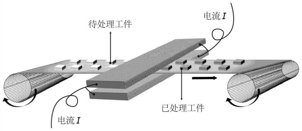
[0044] Embodiment 1: the tempering treatment of No. 45 steel, the quenched raw material of No. 45 steel is placed in image 3 In the typical device diagram shown in the Joule heat plate, the plate is heated to 725°C by electricity, and the workpiece is taken out after holding the heat for 10s, that is, the high temperature tempering process of No. 45 steel is completed. The tempered No. 45 steel obtained has the same properties as Consistent performance with conventional electric furnace heat treatment.

Embodiment 2

[0045] Embodiment 2: The aging treatment of aluminum alloy, the green embryo of 7000 series aluminum alloy is placed in image 3 In the typical device diagram shown in the Joule heat plate, the plate is heated to 425°C with electricity, and the workpiece is taken out after holding the heat for 10s, that is, the aging process of the 7000 series aluminum alloy is completed. The obtained 7000 series aluminum alloy has the same properties as the traditional electric furnace. Heat treatment for consistent strength.

Embodiment 3

[0046] Embodiment 3: the solid solution strengthening of titanium alloy, the annealing raw material TC4 of titanium alloy is placed in image 3 Between the Joule-heated pole plates shown in the typical device diagram, the pole plates are heated to 725°C with electricity, and the workpiece is taken out after holding the heat for 10s, that is, the solid solution strengthening process of the titanium alloy TC4 is completed. The obtained TC4 titanium alloy has the same properties as the traditional electric furnace. Heat treatment for consistent strength.


PUM


Abstract

The invention belongs to the related technical field of metal heat treatment, and discloses a high-temperature adjacent metal heat treatment device and method. The device comprises an upper polar plate and a lower polar plate which are oppositely arranged, wherein the upper polar plate and the lower polar plate are both made of Joule thermal materials; a to-be-treated workpiece is placed between the upper polar plate and the lower polar plate; after current is introduced into the upper polar plate and the lower polar plate, the upper polar plate and the lower polar plate are rapidly heated, and the temperature is transmitted to a heat treatment part; and after the current is cut off, the heat treatment part is cooled. the upper polar plate and the lower polar plate are quickly cooled, so that the temperature in the to-be-treated workpiece is reduced, and heat treatment of the to-be-treated workpiece is realized. In the heat treatment process, the processes of atomic diffusion, phase transformation, grain growth and the like all accord with the heat activation process, faster reaction kinetics can be provided, exponential shortening of the heat treatment time is achieved, the heat treatment method which is high in speed and low in energy consumption and can accurately control the performance of the needed metal material is provided, and the method is wide in applicability and good in batch treatment effect.

Description

technical field [0001] The invention belongs to the technical field related to metal heat treatment, and more specifically relates to a high-temperature close proximity metal heat treatment device and method. Background technique [0002] Heat treatment is the process of heating the metal material to the target temperature at a certain rate, holding it for a certain period of time, and cooling it to room temperature or lower at a certain rate in the medium, so as to achieve the process of adjusting the microstructure and properties of the material. It is mostly used for metal materials, especially steel. The treatment includes normalizing, annealing, quenching, tempering and surface hardening, as well as heat treatment and aging treatment of non-ferrous metals (such as Al alloy, Mg alloy, Ti alloy) and other materials. Heat treatment is a crucial part in the development and application of metal structural parts. The microstructure of the material can be adjusted through reas...

Claims


Application Information

Patent Timeline
IPC IPC(8): C21D1/40C21D11/00
CPCC21D1/40C21D11/00
Inventor 姚永刚
Owner HUAZHONG UNIV OF SCI & TECH
Why Eureka
Try Eureka