Heating system with temperature difference driving air inlet device
A technology of heating system and air intake device, which is applied in the direction of hot gas variable displacement engine device, heating method, gaseous heating fuel, etc., and can solve the problems of high volume, weight and production cost, low thermal efficiency and fuel utilization rate, and heat in the operating space, etc. problems, to achieve the effect of preventing forest fires, high fuel efficiency, and reducing fuel costs
- Summary
- Abstract
- Description
- Claims
- Application Information
AI Technical Summary
Problems solved by technology
Method used
Image
Examples
Embodiment 1
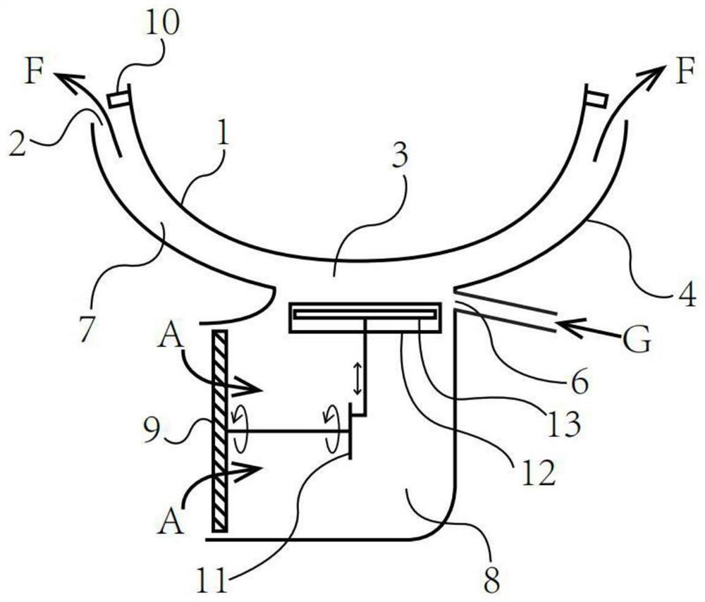
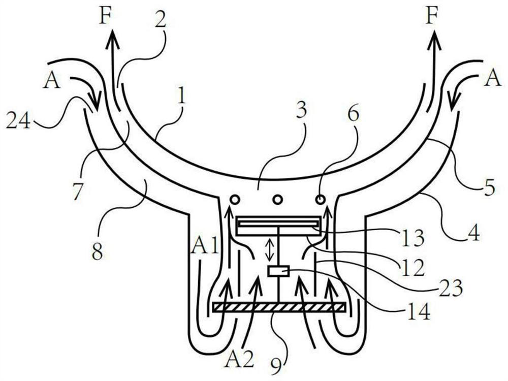
[0065] like figure 1 As shown, a combustion region 3 is provided below the pot body 1, and the gas G delivered in the first fuel inlet 6 and the air A delivered in the Sterling air supply device are combused and heated. 1. The Stirling inletter is mainly composed of a piston chamber 12, a crank structure 11, and a fan 9, and the piston 13 is located within the piston chamber 12. The upper side of the piston cavity 12 acts as a high temperature end of the Stirling system (because the fuel is blended above), the lower side acts as a low temperature of the Stirling system (because the air blown from the fan 9 is just below the air). In order to reduce parts and reduce costs, the fan 9 can simultaneously act as the flywheel of the Stirling system. In order to increase the angle moment of the flywheel, a circle or a ring such as steel or lead or the like can be provided in the outer edge of the fan 9 to increase the wind of the fan 9.
[0066] When the gas is combusted in the combustio...
Embodiment 2
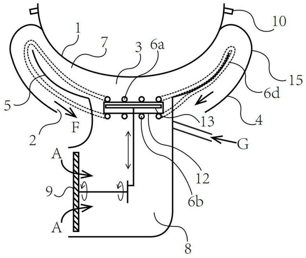
[0076]In order to further improve thermal efficiency, the flue gas passage and the intake passage can be set to each other or cross flow mode to enhance the heat heat of the recovery of export flue gas F and improve the temperature of the input air A or pre-mixing. This package or cross flow mode has many examples in heat transfer. This example is selected Figure 12 The method shown: The second intake passage 8a, the third intake passage 8b is partially wrapped in the second flue gas passage 7A, the third flue gas passage 7b, which is originally figure 1 The housing 4 as an outer surface is disposed such as a thin layer of a thermally conductive heat (such as aluminum sheet, aluminum foil, stainless steel foil, titanium foil, etc.), the isolation layer 5 and / or the new outer surface are set to ceramics, high temperature silicone or high The thermal insulation layer 15 made by materials such as silica aluminum. The insulation insulation layer 15 completely covers and blocks the e...
Embodiment 3
[0089] Figure 4 An embodiment of a straight pot is shown in the present invention is shown.
[0090] In addition to the pot body 1 and the housing 4 are changed to straight, other structures and components are figure 1 There is no significant difference between the Chinese pot body 1 and the housing 4 cross section of the arc or near circular arc.
[0091] Preferably, the housing 4 can be disposed or in addition to an insulation insulation layer therefrom.
[0092] Preferably, the fins can also be provided in the combustion region 3 and / or the first flue gas passage 7 between the pot body 1 and the housing 4 to control the flow rate of flue gas while supporting the pot body 1. / Or flow, increase heat transfer efficiency and fuel utilization.
[0093] Of course, in order to strengthen the waste heat recovery, you can Figure 5 The first flue gas passage 7 is extended; even an extended first flue gas passage 7 is wrapped in the entire housing 4.
[0094] Further, in order to faci...
PUM
 Abstract
Description
Claims
Application Information
 - R&D
- Intellectual Property
- Life Sciences
- Materials
- Tech Scout
- Unparalleled Data Quality
- Higher Quality Content
- 60% Fewer Hallucinations
Browse by: Latest US Patents, China's latest patents, Technical Efficacy Thesaurus, Application Domain, Technology Topic, Popular Technical Reports.
© 2025 PatSnap. All rights reserved.Legal|Privacy policy|Modern Slavery Act Transparency Statement|Sitemap|About US| Contact US: help@patsnap.com


