

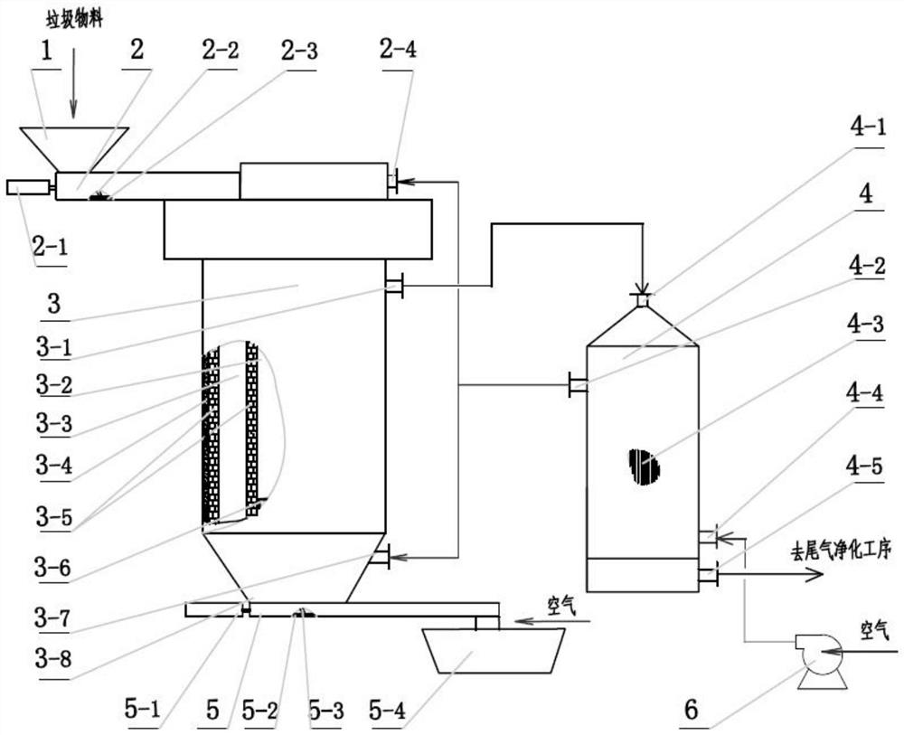
Household garbage thermal storage cracking gasification system
A technology for pyrolysis gasification and domestic waste, applied in the field of domestic waste thermal storage pyrolysis gasification system, can solve the problems such as the inability to guarantee the effective destruction and decomposition of dioxins, the unreasonable process of the exhaust gas purification system, and the inability to maintain the temperature in the furnace continuously. Effective control of slag hardening and coking, easy control of process technical indicators, and humanized design of equipment structure
- Summary
- Abstract
- Description
- Claims
- Application Information
AI Technical Summary
Problems solved by technology
Method used
Image

Examples
Embodiment 1
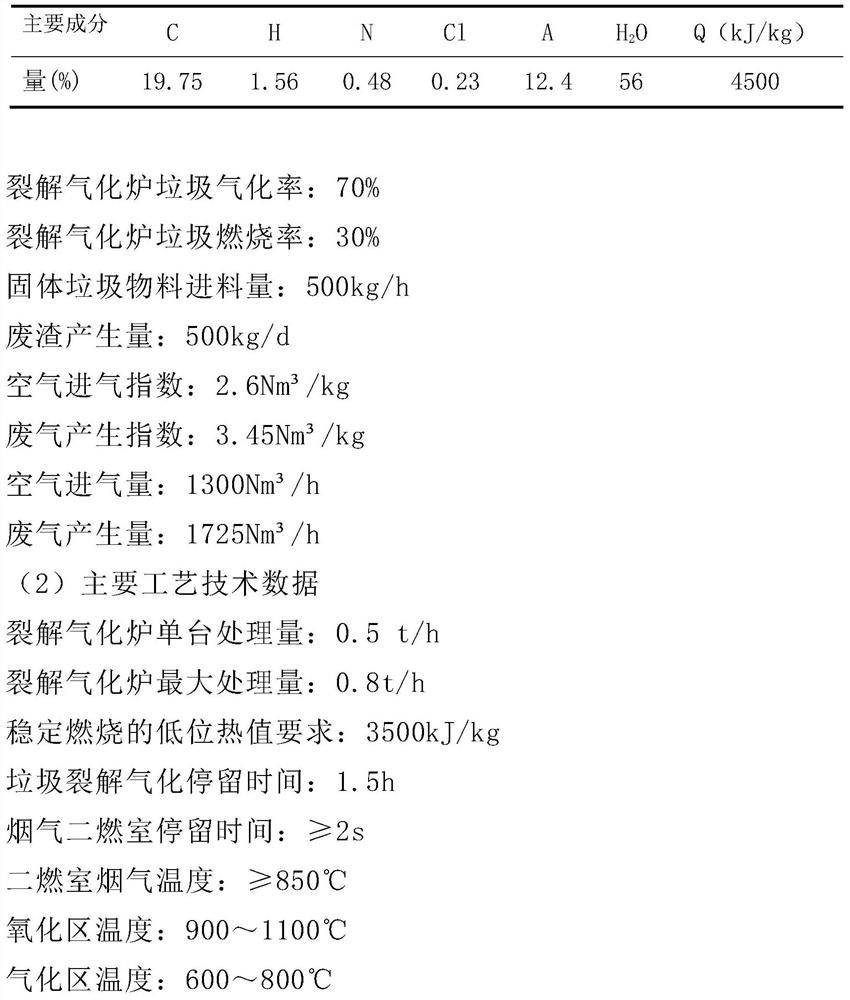
[0087] (1) Design basic data
[0088] The example device is designed according to the township first-level garbage disposal station. For the calculation of the amount of garbage, the population is considered as 10,000 people, the amount of domestic garbage generated per person per day is 1kg, and the total amount of garbage per day is 10t.
[0089] Garbage processing capacity: 10t / d; if the effective working time is 20h per day, then the calculated waste feed volume is 0.5t / h.
[0090] Garbage density: 0.35t / m 3
[0091] Main components and calorific value of garbage: see Table 1
[0092] Table 1 Main components and calorific value of garbage
[0093]
[0094] Cracking zone temperature: 300~600℃
[0095] Drying zone temperature: normal temperature to 300°C
[0096] Allowable load range of pyrolysis gasifier: 60~110
[0097] Economic load range of pyrolysis gasifier: 90~100
[0098] Cracking gasifier efficiency: 75%
PUM
 Abstract
Description
Claims
Application Information