
Cell control device based on multilayer dielectric film

A multi-layer medium and control device technology, which is applied in biochemical cleaning devices, enzymology/microbiology devices, biomass post-treatment, etc., can solve the problems of low success rate, single function, high cost, etc., and reduce light damage , Simple operation, low cost effect

Active Publication Date: 2021-08-31
UNIV OF SCI & TECH OF CHINA
View PDF11 Cites 0 Cited by
  • Summary
  • Abstract
  • Description
  • Claims
  • Application Information

AI Technical Summary

Problems solved by technology

Since the refractive index of the cell is close to that of the liquid environment, and the difference in refractive index is very small, when using optical tweezers to capture a single cell, in order to increase the stability of the capture, it is usually necessary to increase the incident light power, and excessive laser power will cause damage to the cell. Irreversible damage that results in loss of cell activity
[0004] 2. Single function
Based on optical tweezers or photothermal capture cells, usually only single or multiple cells can be captured at a fixed position, and cells cannot be moved to the position we need
[0005] 3. High cost
For example, photothermal manipulation usually requires the processing of micro-nano-scale structures on metal substrates. The success rate of micro-nano processing methods is low, and the recycling rate of metal substrates is low, which leads to higher cost investment.

Method used


Image

  • Cell control device based on multilayer dielectric film
  • Cell control device based on multilayer dielectric film
  • Cell control device based on multilayer dielectric film

Examples


Embodiment Construction

[0019] The present invention will be described in further detail below in conjunction with the accompanying drawings.

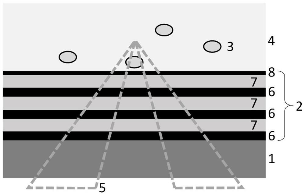
[0020] refer to figure 1 A cell manipulation structure based on a multilayer dielectric film is shown, including: a glass substrate 1 , a multilayer dielectric film 2 , yeast cells 3 , deionized water 4 and circular angularly polarized focused light 5 . Among them, the multilayer dielectric film 2 is made of high refractive index medium Si with a thickness of 132nm 3 N 4 Layer 6 and low refractive index dielectric SiO with a thickness of 145 nm 2 Alternately composed of 7 layers, the top layer Si 3 N 4 Layer 8 is a defect layer with a thickness of 37nm, and the multilayer dielectric film 2 has 7 layers in total. Yeast cells 3 are elliptical cells with a long axis of about 5 μm and a short axis of about 4 μm. After being diluted with deionized water 4 to restore activity, they are dropped on the multilayer dielectric film 2 . Yeast cell 3 density is 1.11...


PUM

PropertyMeasurementUnit
thicknessaaaaaaaaaa
thicknessaaaaaaaaaa
thicknessaaaaaaaaaa

Abstract

The invention discloses a cell control device based on a multilayer dielectric film, which comprises a glass substrate, a multilayer dielectric film, yeast cells, deionized water and annular angular polarization focusing light, and the multilayer dielectric film is deposited on the glass substrate; the yeast cells are diluted with the deionized water, and the diluted yeast cells are dripped on the multilayer dielectric film; the multilayer dielectric film is of a periodic structure and has a surface Bloch wave mode, a light field can be localized on the surface of the multilayer film, the annular angular polarization focused light is utilized to excite Bloch surface waves of the multilayer dielectric film, and the surface waves interfere on the upper surface of the multilayer film to form locally enhanced electric field distribution, so that a single yeast cell can be captured. Due to the inherent loss of the multilayer dielectric film, light energy is converted into heat energy to form local hot spots, and the cells are subjected to heat convection force and thermophoresis force, so that the close arrangement of a plurality of yeast cells is realized. According to the device, the medium multilayer film is utilized for the first time to simultaneously capture single yeast cells and densely arrange a large number of yeast cells, the practicability is high, and the operation is simple.

Description

technical field [0001] The invention relates to the technical field of cell capture and manipulation, in particular to a cell manipulation device based on a multilayer medium membrane. Background technique [0002] Cell capture and manipulation technologies play a vital role in the fields of physics, biochemistry, and biomedicine, and have received extensive attention. Cell capture methods can be briefly summarized into two categories, namely optical tweezers and photothermal manipulation. First of all, optical tweezers use the light scattering force and gradient force of tightly focused beams to trap single particles or cells. Secondly, photothermal manipulation is to use light-thermal conversion to convert light energy into heat energy, and use thermal convection, thermophoresis, thermoelectric field, etc. induced by temperature gradients to simultaneously capture multiple cells in a wide range. The above-mentioned capture technology has certain limitations in practical ...

Claims


Application Information

Patent Timeline
Patent Type & Authority Applications(China)
IPC IPC(8): C12M1/42C12M1/00G02B21/32
CPCC12M35/02C12M25/02G02B21/32
Inventor 陆凤雅张斗国
Owner UNIV OF SCI & TECH OF CHINA
Learn More