Vacuum reflow soldering positive and negative pressure combined welding process

A welding process and vacuum reflow technology, applied in welding equipment, manufacturing tools, metal processing equipment, etc., can solve problems such as damaged weldments, welding defects, and long air bubble discharge time

Active Publication Date: 2021-09-14
成都共益缘真空设备有限公司
View PDF23 Cites 0 Cited by
  • Summary
  • Abstract
  • Description
  • Claims
  • Application Information

AI Technical Summary

Problems solved by technology

[0003] The existing vacuum reflow soldering process is as follows: vacuuming - filling nitrogen to negative pressure 50000PA ~ 100000PA - heating to 160 ~ 180°C - constant temperature and then raising the temperature to melting point temperature 217°C - heating to 245 ~ 260°C - constant temperature 0 ~ 10 seconds—vacuumize—constant temperature for 0 to 100 seconds—cool to 200°C—normal temperature—fill nitrogen to normal pressure—take parts, but this process has the following defects in actual use: the bubbles in the solder are under negative pressure. It cannot be broken by itself, and finally leads to a large void rate. When the air bubbles in the solder are under negative pressure, the melting temperature of the solder will increase, and the bubble discharge time will be longer. Therefore, in order to ensure the void rate as much as possible, we can only extend the vacuum. time, the solder process and the temperature resistance time of the device are strictly required. If it is too long, welding defects will occur and the weldment will be damaged.

Method used


Image

  • Vacuum reflow soldering positive and negative pressure combined welding process
  • Vacuum reflow soldering positive and negative pressure combined welding process
  • Vacuum reflow soldering positive and negative pressure combined welding process

Examples


Embodiment

[0065] Such as Figure 1-6 As shown, this embodiment provides a vacuum reflow soldering combined positive and negative pressure welding process, including the following steps:

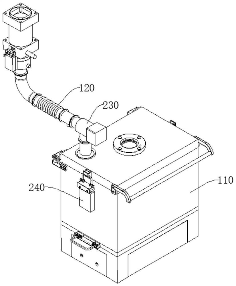
[0066] Step S1: Prepare for equipment commissioning in the vacuum chamber 110;

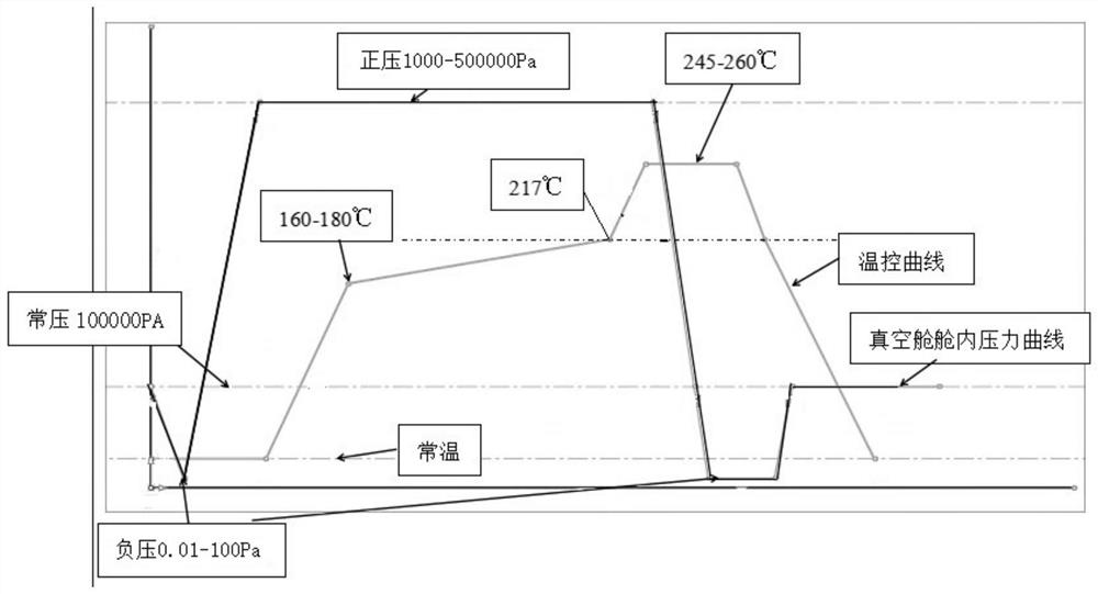
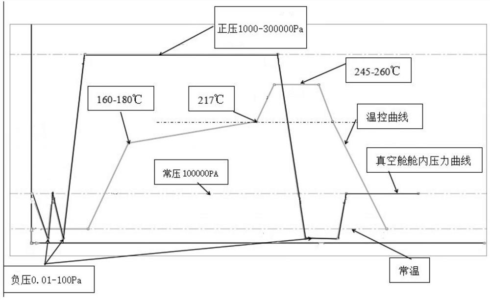
[0067] Step S2: The PLC controller controls the vacuum damper valve 230 to open, and starts vacuuming at room temperature. The vacuuming time is 10 to 120 seconds. When the PLC controller detects through the pressure sensor that the pressure in the vacuum chamber 110 is less than or equal to When the preset pressure value of negative pressure is 0.05-100PA, close the vacuum damper valve 230;

[0068] Step S3: Open the reducing agent valve by the PLC controller, and fill the reducing agent into the vacuum chamber 110 at normal temperature to a positive pressure of 1,000-500,000 PA. When the PLC controller detects that the vacuum chamber 110 reaches 1,000-500,000 PA through the pressure sensor When the positive pressure va...


PUM

PropertyMeasurementUnit
melting pointaaaaaaaaaa

Abstract

The invention discloses a vacuum reflow soldering positive and negative pressure combined welding process, and relates to the technical field of vacuum reflow soldering. The process comprises the following steps that debugging preparation is carried out on vacuum cabin equipment; vacuumizing is carried out in a normal temperature state until the pressure in a vacuum cabin is smaller than or equal to a preset pressure value of 0.05-100PA of negative pressure; the vacuum cabin is filled with a reducing agent into in a normal temperature state until the positive pressure is 1000-500000PA; heating is carried out to reach 160-180 DEG C; then heating is carried out to reach the melting point of welding flux of 217 DEG C; then heating is carried out to reach 245-260 DEG C, and the constant temperature is kept for 1-30 seconds; vacuumizing is carried out for 20-30 seconds, and the vacuum degree in the vacuum cabin is maintained at the negative pressure ranging from 0.01 PA to 100 PA; cooling is carried out; the internal pressure of the vacuum cabin reaches normal pressure; and when it is detected that the preset cooling temperature is reached, a weldment is taken out. According to the process, firstly, under the action of positive pressure, bubbles in the welding flux are removed, then when vacuumizing is carried out to reach the negative pressure, the bubbles in the welding flux are removed again, the discharging time of the bubbles is greatly shortened in a positive pressure and negative pressure combined mode, and therefore the voidage of the welding flux is far lower than the voidage in a traditional process.

Description

technical field [0001] The invention relates to the technical field of vacuum reflow soldering, in particular to a positive and negative pressure combined welding process of vacuum reflow soldering. Background technique [0002] Vacuum reflow soldering process is a reflow soldering technology that introduces a vacuum environment during the reflow soldering process. Compared with traditional reflow soldering, vacuum reflow soldering creates a vacuum environment after the product enters the reflow area, and the atmospheric pressure can drop to 500Pa Below, and keep for a period of time, so as to realize the combination of vacuum and reflow soldering. At this time, the solder joint is still in a molten state, while the external environment of the solder joint is close to vacuum. Due to the pressure difference between the inside and outside of the solder joint, the air bubbles in the solder joint It can overflow from it, and the void rate of solder joints will be reduced. Low vo...

Claims


Application Information

Patent Timeline
Patent Type & Authority Applications(China)
IPC IPC(8): B23K1/00
CPCB23K1/00
Inventor 许建国
Owner 成都共益缘真空设备有限公司
Why Eureka
Try Eureka