Cell micro-injection device and robust impedance control method thereof
A microinjection and impedance control technology, applied in the fields of biomedical engineering and precision control, can solve the problems of mechanism fatigue failure, unstable steady-state error, inability to compliant mechanism to achieve stiffness ratio, etc., to improve the success rate and reduce assembly. Error, avoid the effect of system instability
- Summary
- Abstract
- Description
- Claims
- Application Information
AI Technical Summary
Problems solved by technology
Method used
Image

Examples
Embodiment Construction
[0033] The technical solution of the present invention will be further described below in conjunction with the accompanying drawings.
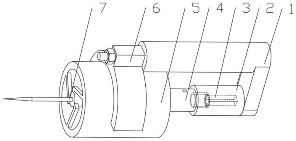
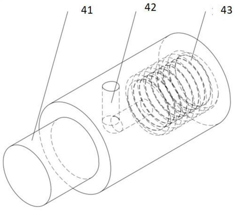
[0034] Such as Figure 1 to Figure 4 As shown, the cell microinjection device of the present invention includes a connecting rod 1 , a packager 2 , a piezoelectric driver 3 , an injector 4 , a hub type compliance mechanism 5 , a fixed chuck 6 , and a microinjection needle 7 .
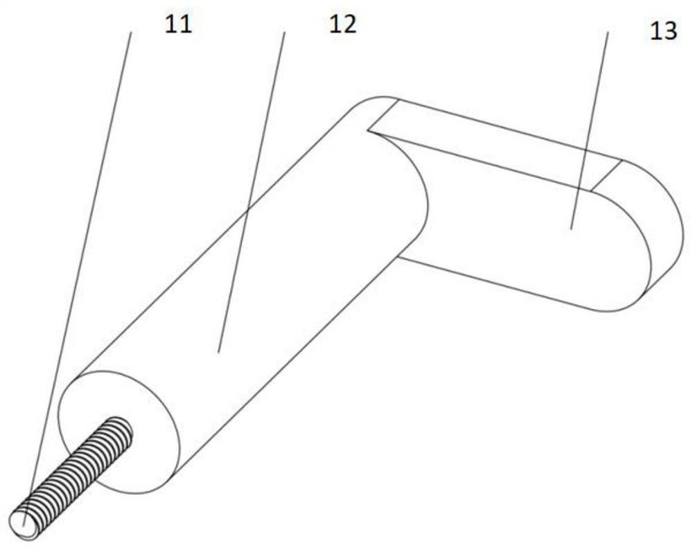
[0035] The connecting rod 1 includes a threaded part 11, a connecting part 12, and a pressing part 13, wherein the threaded part 11 is connected with the fixed collet 6, and the fixed collet 6 is fixed on the outside of the hub type compliance mechanism 5, and a threaded part 11 is also provided with a Nut, by rotating the nut to adjust the relative position of the connecting rod 1 and the fixed chuck 6; the pressing part 13 is against one end of the packager 2, and when the nut is tightened, the piezoelectric driver 3 in the packager 2 will be generated The effect of ...
PUM
 Abstract
Description
Claims
Application Information
 - R&D
- Intellectual Property
- Life Sciences
- Materials
- Tech Scout
- Unparalleled Data Quality
- Higher Quality Content
- 60% Fewer Hallucinations
Browse by: Latest US Patents, China's latest patents, Technical Efficacy Thesaurus, Application Domain, Technology Topic, Popular Technical Reports.
© 2025 PatSnap. All rights reserved.Legal|Privacy policy|Modern Slavery Act Transparency Statement|Sitemap|About US| Contact US: help@patsnap.com