Blast furnace gas sulfur resource utilization device

A blast furnace gas and resource technology, which is applied in the field of blast furnace gas sulfur resource utilization devices, can solve the problems of low utilization rate of adsorbents, large bed pressure loss, large loading capacity of microcrystalline adsorbents, etc.

Pending Publication Date: 2021-11-05
上海展恒环保科技有限公司
View PDF4 Cites 4 Cited by
  • Summary
  • Abstract
  • Description
  • Claims
  • Application Information

AI Technical Summary

Problems solved by technology

For example, patent CN110252069A discloses a method for dry desulfurization of blast furnace gas. This method uses microcrystalline materials to adsorb organic sulfur and inorganic sulfur species, and can remove sulfides in blast furnace gas in one step. However, the loading of microcrystalline adsorption materials is large. , high investment, large bed pressure loss, high operating energ

Method used


Image

  • Blast furnace gas sulfur resource utilization device
  • Blast furnace gas sulfur resource utilization device

Examples


Embodiment 1

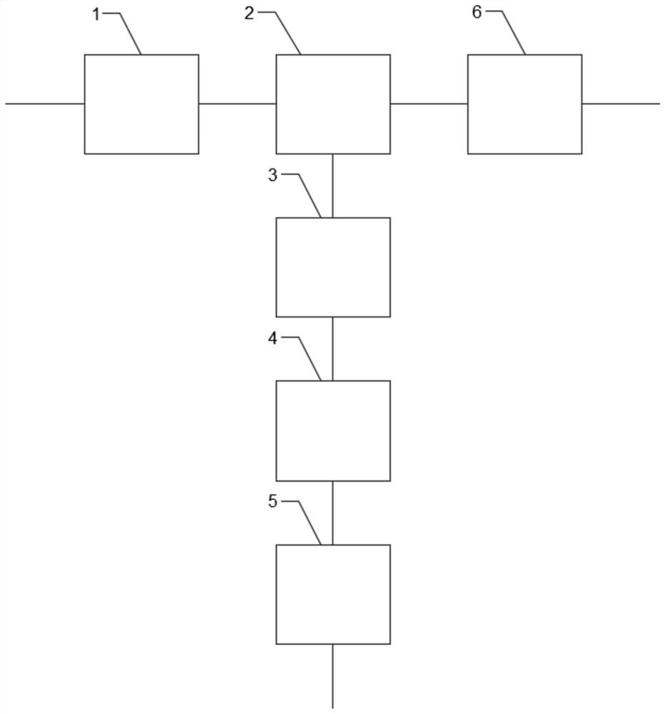
[0043] Such as figure 1 As shown, the blast furnace gas sulfur resource utilization device provided by the embodiment of the present invention includes: a pretreatment unit 1 , an adsorption / desorption unit 2 , a delivery unit 6 , a heating unit 3 , a catalytic unit 4 and a condensation recovery unit 5 .

[0044] Among them, the pretreatment unit 1 includes a plurality of functional sub-modules, which respectively realize different functions, such as dechlorination, cooling and dehydration, heating and dehumidification, filtration and deoxidation, and the like. The inlet of the pretreatment unit 1 is in communication with the blast furnace gas to be treated.

[0045] The inlet of the adsorption / desorption unit 2 is connected to the outlet of the pretreatment unit 1, and the adsorption / desorption unit 2 includes at least two sub-modules, such as an adsorption module and a desorption module, which are used to separate the sulfur-containing substances of the blast furnace gas . ...

Embodiment 2

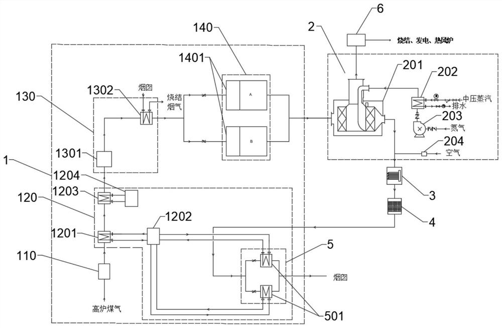
[0053] This embodiment is an optional implementation of the device for utilizing sulfur resources of blast furnace gas in Embodiment 1. Such as figure 2 As shown, in this embodiment, the pretreatment unit 1 includes a dechlorination module 110 , a cooling module 120 , a dehumidification module 130 and a filter deoxygenation module 140 . Wherein, the inlet of the pretreatment unit 1 receives blast furnace gas to be treated, and the received blast furnace gas first enters the dechlorination module 110, and the dechlorination module 110 is used for removing chlorine-containing substances. After the blast furnace gas passes through the dechlorination module 110, it needs to be cooled by the cooling module 120. The cooling can condense the unsaturated water in the gas into supersaturated liquid water, and then remove it through the precision demister, so that the subsequent reheating process The relative humidity of the gas is reduced, thereby ensuring the adsorption efficiency o...


PUM

PropertyMeasurementUnit
Meshaaaaaaaaaa

Abstract

The embodiment of the invention discloses a blast furnace gas sulfur resource utilization device. The blast furnace gas sulfur resource utilization device comprises a pretreatment unit, an adsorption/desorption unit, a conveying unit, a heating unit, a catalysis unit and a condensation recovery unit; an inlet of the pretreatment unit is communicated with to-be-treated blast furnace gas, and the pretreatment unit is used for dechlorinating the to-be-treated blast furnace gas, cooling to remove water, heating to dehumidify and filtering to deoxidize; an inlet of the adsorption/desorption unit is communicated with an outlet of the pretreatment unit, and the adsorption/desorption unit is used for separating sulfur-containing substances of blast furnace gas; and the conveying unit is arranged at an adsorption gas outlet of the adsorption/desorption unit and is used for conveying clean coal gas to a gas using point. According to the blast furnace gas sulfur resource utilization device, low-investment and low-energy-consumption desulfurization of the blast furnace gas can be realized, and sulfur-containing species resources are utilized.

Description

technical field [0001] Embodiments of the present invention relate to the technical field of energy conservation and environmental protection, and in particular to a device for utilizing sulfur resources of blast furnace gas. Background technique [0002] Blast furnace gas is an industrial gas produced by iron and steel enterprises in blast furnace ironmaking. The output per ton of iron is about 1500-2000Nm3, and the main components are CO2 (6-15%), CO (28-35%), H2 (2-8 %), N2 (55-60%), CxHy (0.2-0.5%), a large amount of dust, water vapor, a small amount of chloride and a small amount of sulfur-containing species, among which the sulfur-containing species are mainly COS and H2S, with a concentration of 80-220mg / m3, calorific value 3000-4000KJ / Nm3, furnace temperature 100-160℃. [0003] Blast furnace gas desulfurization and purification is a key environmental protection and emission reduction industry promoted by the state. The latest policy "Opinions on Promoting the Imple...

Claims


Application Information

Patent Timeline
IPC IPC(8): C10K1/00C10K1/04C10K1/20C10K1/32B01D53/00B01D53/86B01D53/48
CPCC10K1/002C10K1/04C10K1/32C10K1/004C10K1/20B01D53/005B01D53/8603B01D2255/20761B01D2255/20738B01D2255/2073B01D2255/20746B01D2255/2065B01D2255/20723B01D2255/20792B01D2258/02B01D2255/70Y02A50/20Y02P20/10
Inventor 倪彪黄樊张俊
Owner 上海展恒环保科技有限公司
Why Eureka
Try Eureka