System and method for treating organic polluted solid waste through rapid pyrolysis

A technology for organic pollution and solid waste, applied in combustion methods, separation methods, chemical instruments and methods, etc., can solve the problems of large amount of waste gas, high disposal cost, and high difficulty in operating molten salt circulation system, reducing operating costs and improving The effect of pyrolysis rate

Pending Publication Date: 2021-11-09
无锡爱普特设备科技有限公司
View PDF5 Cites 1 Cited by
  • Summary
  • Abstract
  • Description
  • Claims
  • Application Information

AI Technical Summary

Problems solved by technology

[0006] The above three patents all use an external heating source to thermally decompose organic matter in waste salt. The patent with the publication number CN106801874A uses microwaves as energy for indirect heating, but it has high disposal costs and low energy utilization of microwave generators. Disadvantages such as difficulty in separating microwave absorbing medium particles
The patent with the publication number CN107321755A adopts furnace top cloth, and the high-temperature flue gas generated by natural gas combustion can realize waste salt drying, preheating and burning of organic matter in waste salt during the process of rising in the furnace, and the molten salt collected at the bottom of the furnace is discharged from the molten salt outlet. Outflow, the flue gas of the system is in direct contact with the waste salt, the amount of waste gas generated is large, the contact time between the waste salt and the hot air is limited, the temperature of the salt itself does not reach the expected temperature, and the content of residual organic components is difficult to control, etc.
The patent with the publication number CN204185249U uses natural gas or diesel as the heating energy, and uses heat transfer oil and liquid molten salt as the heat exchange medium for indirect heating, but the equipment structure is complicated, and the operation of the molten salt circulation system is difficult.

Method used


Image

  • System and method for treating organic polluted solid waste through rapid pyrolysis

Examples


Embodiment Construction

[0025] The present invention will be further described below in conjunction with the accompanying drawings.

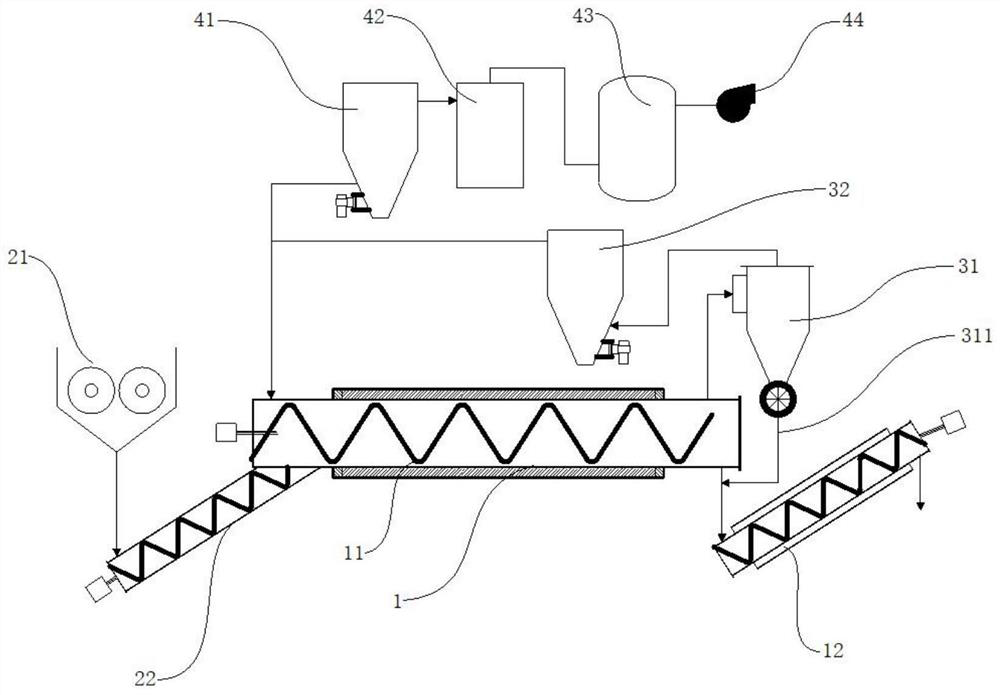
[0026] as attached figure 1 : A fast pyrolysis treatment system for organically polluted solid waste, comprising a material pretreatment unit, a fast pyrolysis reaction unit, a thermal oxidation unit and a tail gas treatment unit; the discharge end of the material pretreatment unit corresponds to the fast pyrolysis reaction unit The feed end of the feed; the fast pyrolysis reaction unit is composed of a horizontally arranged pyrolysis tube 1, and the inside of the pyrolysis tube 1 is provided with an auger 11, and the auger 11 is driven to rotate by an engine; the fast pyrolysis The outlet end of the reaction unit is connected to the inlet end of the thermal oxidation unit, the material separation end of the thermal oxidation unit is connected to the outlet end of the fast pyrolysis reaction unit, and the outlet end of the thermal oxidation unit is connected to the tai...


PUM


Abstract

The invention discloses a system and method for treating organic polluted solid waste through rapid pyrolysis. The system comprises a material pretreatment unit, a rapid pyrolysis reaction unit, a thermal oxidation unit and a tail gas treatment unit, wherein the discharging end of the material pretreatment unit corresponds to the feeding end of the rapid pyrolytic reaction unit; the rapid pyrolysis reaction unit is composed of a horizontally-arranged pyrolysis pipe, and an auger is arranged in the pyrolysis pipe and driven by an engine to rotate; and the gas outlet end of the rapid pyrolysis reaction unit is connected to the gas inlet end of the thermal oxidation unit, the material separation end of the thermal oxidation unit is connected to the discharge end of the rapid pyrolysis reaction unit, and the gas outlet end of the thermal oxidation unit is connected to the gas inlet end of the tail gas treatment unit. When a hydrocarbon concentration is set to be higher than a set value, a pure oxygen oxidizer is lowered or external fuel supply is stopped, so solid waste pyrolysis gas serves as a fuel source, and operation cost is reduced.

Description

technical field [0001] The invention relates to the technical field of organic pollution solid waste treatment, in particular to a rapid pyrolysis treatment system and treatment method for organic pollution solid waste. Background technique [0002] In the organic synthesis industry, fine chemical industry, pesticide industry and many other industries, it is often necessary to purify the synthetic product or intermediate product by alkalization and acidification in the product purification stage, and use the two-step reaction of the target NaOH and HCl to complete the purification and Treatment, such as the synthesis of organic chemicals such as pyrithione and 1,2-benzisothiazolin-3-one, the final result of the two-step reaction of alkalization and acidification is the neutralization of NaOH and HCl to produce NaCl solution However, the NaCl solution often contains a wide variety of organic synthesis products, which are often quite toxic and difficult to handle. Therefore, t...

Claims


Application Information

Patent Timeline
Patent Type & Authority Applications(China)
IPC IPC(8): C10B53/00C10B57/00C10B49/02C10B31/00B01D45/12C10L3/00F23G7/06
CPCC10B53/00C10B49/02C10B31/00C10B57/00F23G7/06B01D45/12C10L3/00F23G2209/14
Inventor 周冲
Owner 无锡爱普特设备科技有限公司
Why Eureka
Try Eureka