Humidification system based on wind energy

A humidification system and wind energy technology, applied in the field of wind energy, can solve the problems of reducing the area of ​​humidification, unable to combine water vapor, and unable to dissipate water vapor, so as to avoid uneven humidification, expand the range of humidification, and achieve the effect of uniform and thorough humidification of water flow

Inactive Publication Date: 2021-11-16
祁兴刚
View PDF0 Cites 0 Cited by
  • Summary
  • Abstract
  • Description
  • Claims
  • Application Information

AI Technical Summary

Problems solved by technology

[0005] Aiming at the deficiencies of the prior art, the present invention provides a humidification system based on wind energy, which solves the problem that the existing wind energy-based humidification device has a fast flow of air during use and cannot fully combine with water vapor, resulting in that the water vapor cannot follow the The airflow is distributed to reduce the area of ​​humidification

Method used


Image

  • Humidification system based on wind energy
  • Humidification system based on wind energy
  • Humidification system based on wind energy

Examples


Embodiment 1

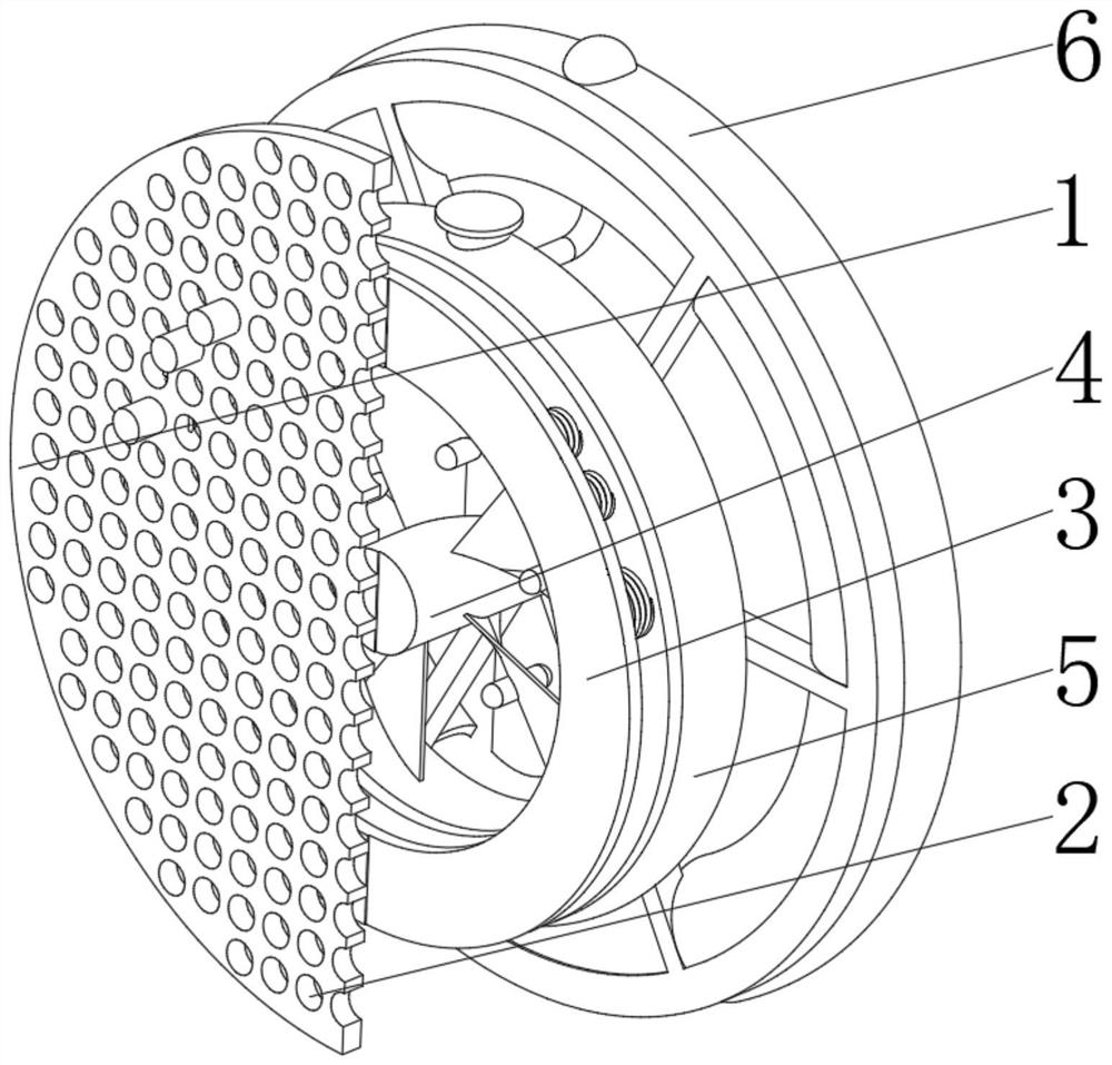
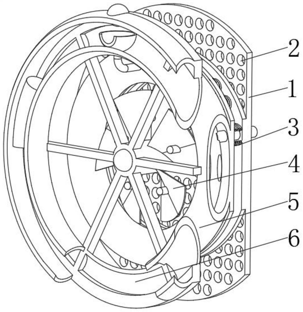
[0044] see Figure 1-6 , the present invention provides a technical solution: a humidification system based on wind energy, specifically comprising:

[0045]Mounting plate 1, the mounting plate 1 has a circular plate body, and an airflow hole 2 provided on the surface of the circular plate body, and a flow guiding device 3 installed on the back of the airflow hole 2, and installed in the middle position on the back of the circular plate body And the wind energy device 4 located between the flow guide devices 3, and the evaporation device 5 installed on the back of the flow guide device 3, and the liquid injection device 6 installed at the end of the wind energy device 4 away from the circular plate body, through the airflow hole 2 and the installation The arrangement of the plate 1 filters the air flow, separates the impurities in the air flow, realizes the purification of the air flow, and slows down the flow speed of the air flow at the same time, so that the air flow can fu...

Embodiment 2

[0056] see Figure 1-6 On the basis of Embodiment 1, the present invention provides a technical solution: a wind energy-based humidification system, comprising the following steps,

[0057] Step 1: Fix and install the equipment through the mounting plate 1, and at the same time assemble and fix each component, and inject water into the water storage ring 51 through the water filling port 55;

[0058] Step 2: When the airflow is flowing, the impact force of the airflow will impact the wind energy leaf plate 42, so that the wind energy leaf plate 42 drives the central axis column 41 to rotate;

[0059] Step 3: The rotation of the wind energy plate 42 promotes the flow of the air flow, and the rotation of the wind energy plate 42 drives the magnet post 43 to change its position;

[0060] Step 4: the rice-shaped coil strut 62 cuts the magnetic field lines of the magnet post 43, and the rice-shaped coil strut 62 thus generates a current to supply energy;

[0061] Step 5: The curr...


PUM


Abstract

The invention discloses a humidification system based on wind energy. The humidification system based on the wind energy specifically comprises an installation plate, an airflow hole formed in the surface of a circular plate body, a flow guide device installed on the back surface of the airflow hole, an evaporation device installed on the back surface of the flow guide device, and a liquid injection device installed at one end, away from the circular plate body, of a wind energy device, wherein the evaporation device comprises a water storage ring, a water drawing ring installed at the middle position of an inner cavity of an annular sleeve, and a water drawing rod installed at the side, close to the flow guide device, of the water drawing ring. The humidification system based on the wind energy further comprises an auxiliary water injection opening which is formed in the top of the side, away from the flow guide device, of the outer surface of the annular sleeve. The invention relates to the technical field of wind energy. Airflow is filtered through formation for airflow hole and arrangement for the installation plate, impurities in the airflow are separated, purification for the airflow is realized, meanwhile, the flowing speed of the airflow is reduced, the airflow makes full contact with water, and indoor humidification is realized.

Description

technical field [0001] The invention relates to the technical field of wind energy, in particular to a humidification system based on wind energy. Background technique [0002] With the development of industrialization and the continuous increase of population in our country, the pollution is also becoming more and more serious. In buildings, the pollutants produced by more and more gorgeous decorations and other factors have a serious impact on indoor air quality. These pollutants have serious harm to the human respiratory system, cardiovascular system and nervous system. In the car, due to the infiltration of exhaust gas from the engine and the emission of interior decoration materials, pollutants such as VOCs (formaldehyde, acetaldehyde, acetic acid, benzene, ammonia, nitrogen oxides, acetone, xylene, etc.) sometimes reach fairly high concentration. On the other hand, the content of dust in the air is also increasing, resulting in further deterioration of the indoor env...

Claims


Application Information

Patent Timeline
Patent Type & Authority Applications(China)
IPC IPC(8): F24F6/10F24F8/108F24F13/22B60H3/02B60H3/06H02K7/18
CPCF24F6/10F24F8/108F24F13/222B60H3/022B60H3/0608H02K7/1823H02K7/183
Inventor 祁兴刚
Owner 祁兴刚
Why Eureka
Try Eureka