Light receiving device
A technology of optical reception and optical signal, which is applied in electromagnetic receivers, optical fiber transmission, gain control, etc., can solve the problems of large volume, high cost, and limited dynamic range of optical communication systems, and achieve the effect of improving link performance
- Summary
- Abstract
- Description
- Claims
- Application Information
AI Technical Summary
Problems solved by technology
Method used
Image

Examples
no. 1 example
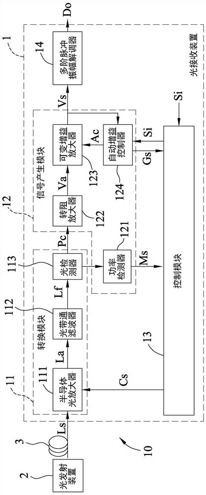
[0070] see figure 1 , an embodiment of the optical receiving device 1 of the present invention is suitable for an optical communication system 10 . The optical communication system 10 includes a light emitting device 2 and an optical fiber 3 . The light emitting device 2 is used for emitting a multi-order pulse amplitude modulation (PAM-N) optical signal Ls, and transmits the optical signal Ls to the light receiving device 1 through the optical fiber 3 . The optical signal Ls is an at least fourth-order multi-order pulse amplitude modulation signal. In this embodiment, the optical signal Ls is taken as an example of a fourth-order pulse amplitude modulation signal, but it is not limited to this.
[0071] The light receiving device 1 of this embodiment includes a conversion module 11 , a signal generation module 12 , a control module 13 , and a multi-order pulse amplitude demodulator 14 .
[0072]The conversion module 11 is used for receiving the optical signal Ls from the o...
no. 2 example
[0090] see Figure 7 , the second embodiment of the optical receiving device 1 of the present invention is similar to the first embodiment, the difference between the two is that in the second embodiment: (1) a conversion module 11a is used to replace the first embodiment. The conversion module 11 (see figure 1), the conversion module 11a includes a photoelectric converter 114 and a bias voltage generator 115; and (2) the power detector 121 is electrically connected to the photoelectric converter 114 rather than the photodetector 113 (see figure 1 ).
[0091] The photoelectric converter 114 receives a bias voltage Vb and is used to receive the optical signal Ls from the optical fiber 3 . The photoelectric converter 114 adjusts a gain of itself according to the bias voltage Vb (for example, when the bias voltage Vb increases, the gain of the photoelectric converter 114 increases accordingly), and performs photoelectric conversion on the optical signal Ls and amplification to...
no. 3 example
[0095] see Figure 8 , the third embodiment of the optical receiving device 1 of the present invention is used in another optical communication system, and the other optical communication system is a wavelength division multiplexing (Wavelength Division Multiplexing, WDM) transmission system. The third embodiment is similar to the first embodiment, except that in the third embodiment: (1) the optical signal Ls has a plurality of multi-order pulse amplitude modulation signals each of which is at least a fourth order (In this embodiment, it is assumed that each multi-level pulse amplitude modulation signal is a fourth-order pulse amplitude modulation signal, but it is not limited to this); (2) a plurality of photocurrent parts Pc1-Pcn constitute the photocurrent Pc ( See figure 1 ), multiple gain signal parts Gs1~Gsn form the gain signal Gs (see figure 1 ), a plurality of measurement signal parts Ms1-Msn form the measurement signal Ms, and a plurality of voltage signal parts V...
PUM
 Abstract
Description
Claims
Application Information
 - R&D
- Intellectual Property
- Life Sciences
- Materials
- Tech Scout
- Unparalleled Data Quality
- Higher Quality Content
- 60% Fewer Hallucinations
Browse by: Latest US Patents, China's latest patents, Technical Efficacy Thesaurus, Application Domain, Technology Topic, Popular Technical Reports.
© 2025 PatSnap. All rights reserved.Legal|Privacy policy|Modern Slavery Act Transparency Statement|Sitemap|About US| Contact US: help@patsnap.com