
Self-disturbance laser additive manufacturing method

A laser additive and manufacturing method technology, applied in the direction of manufacturing tools, additive manufacturing, additive processing, etc., can solve the problems of complex production equipment and preparation process, difficult to achieve vibration and stirring effect, increase production cost, etc., to reduce porosity , shorten the time required for processing, improve the effect of toughness

Pending Publication Date: 2021-12-31
EZHOU INST OF IND TECH HUAZHONG UNIV OF SCI & TECH +1
View PDF6 Cites 7 Cited by
  • Summary
  • Abstract
  • Description
  • Claims
  • Application Information

AI Technical Summary

Problems solved by technology

[0003] However, the SLM technology based on "linear scanning" has the following problems: First, because the interaction time between the high-speed "linear" scanning laser and the powder is only 10 -4 s-10 -5 s, the molten pool generated by the laser during the forming process is 10 -4 mm 3 Size-level micro-melt pool, laser power density up to 10 5 W / cm 2 -10 7 W / cm 2 , cooling rate up to 10 6 K / s-10 8 K / s, temperature gradient at 10 5 ℃ / mm level
However, the SLM forming process is carried out in a closed cavity, and the use of additional physical external fields leads to more complex production equipment and preparation processes, which greatly increases production costs; at the same time, it is difficult to achieve uniform vibration by applying physical external fields when preparing large precision and complex parts Stirring effect, so the above techniques cannot be applied to SLM forming

Method used


Image

  • Self-disturbance laser additive manufacturing method
  • Self-disturbance laser additive manufacturing method
  • Self-disturbance laser additive manufacturing method

Examples


Embodiment 1

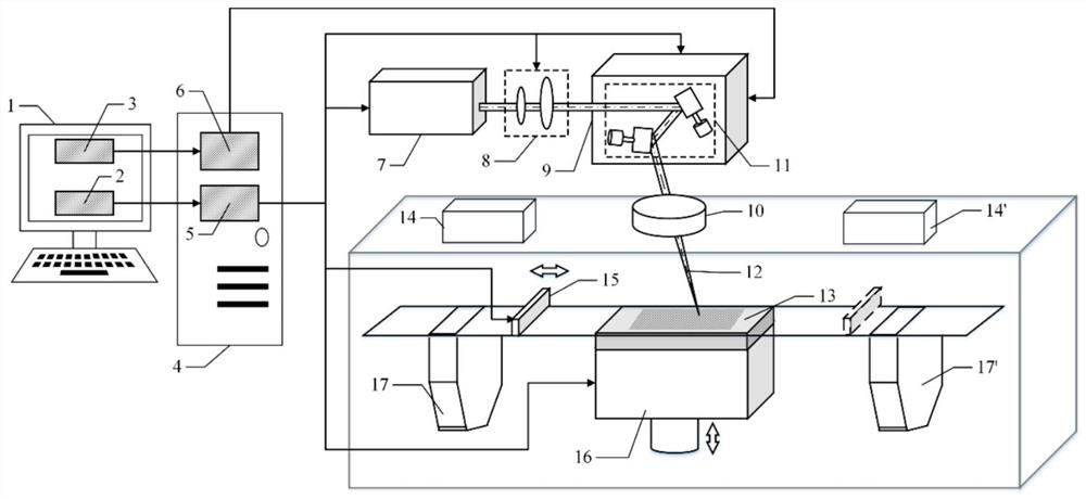
[0123] Such as image 3 As shown, the self-disturbance laser additive manufacturing system provided by the present invention is a two-way powder spreading method, and the self-disturbance laser additive manufacturing system includes a system software 1, a controller 4, a laser 7, a beam expander 8, and a scanning galvanometer 9 , focusing mirror 10, substrate 13, first and second powder feeding devices 14, 14', powder spreading device 15, forming cylinder 16 and first and second powder recovery devices 17, 17'. System software 1 includes forming process parameter control software 2 and self-disturbance parameter control software 3, controller 4 includes forming process parameter controller 5 and self-disturbance parameter controller 6, wherein forming process parameter control software 2 and forming process parameter controller 5 It is used to set forming process parameters such as laser power P, scanning distance H, phase angle θ, and motion parameters such as layer thickness...

Embodiment 2

[0130] Such as Figure 4 As shown, the self-disturbance laser additive manufacturing system provided by the present invention is a two-way powder spreading method, and the self-disturbance laser additive manufacturing system includes a system software 1, a controller 4, first and second lasers 7, 7', a second 1. Second beam expanders 8, 8', first and second scanning galvanometers 9, 9', first and second focusing mirrors 10, 10', substrate 13, first and second powder feeding devices 14, 14', powder spreading device 15, forming cylinder 16, and first and second powder recovery devices 17, 17'. The system software 1 includes a forming process parameter control software 2 and a self-disturbance parameter control software 3 , and the controller 4 includes a forming process parameter controller 5 and a self-disturbance parameter controller 6 . Among them, the forming process parameter control software 2 is connected with the forming process parameter controller 5, and is used to se...

Embodiment 3

[0138] The Ti-43Al-9V-0.5Y(at.%) alloy thin-walled sample was prepared by using the above-mentioned single-beam self-disturbance laser additive manufacturing system. The scanning strategy was circular periodic disturbance, and the length of the sample was 10mm. The test raw material is Ti-43Al-9V-0.5Y (at.%) alloy powder blown by gas atomization, and the particle size of the powder is 15-53 μm. In order to ensure the fluidity of the powder, the alloy powder was kept in a vacuum oven at 100 °C for 1 h before the test. The self-disturbance laser additive manufacturing method comprises the following steps:

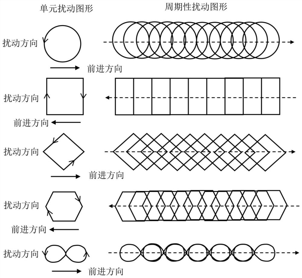
[0139] Step 1: Determine that the laser motion trajectory is a periodic circular disturbance, and set the self-disturbance parameters: the radius of the circle is 1mm, the number of disturbances is 100, the distance between two adjacent circles is the same as 0.1mm, and the disturbance speed is 20mm / s. The disturbance direction is clockwise, then the position coordinates of ...


PUM


Abstract

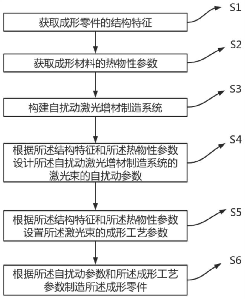
The invention discloses a self-disturbance laser additive manufacturing method. The method comprises the following steps of: obtaining structural characteristics of a formed part; obtaining thermophysical parameters of a formed material; constructing a self-disturbance laser additive manufacturing system; designing self-disturbance parameters of a laser beam of the self-disturbance laser additive manufacturing system according to the structural characteristics and the thermophysical parameters; setting forming process parameters of the laser beam according to the structural characteristics and the thermophysical parameters; and manufacturing the formed part according to the self-disturbance parameters and the forming process parameters. According to the self-disturbance laser additive manufacturing method, one-dimensional linear scanning of the laser beam in the prior art is converted into periodic two-dimensional graphic disturbance, stirring of a liquid molten pool is realized under the condition of no additional physical field, the functions of homogenizing a microstructure, refining grains, inhibiting element burning loss, reducing metallurgical defects such as cracks and air holes, increasing the size of the molten pool and shortening the machining time are achieved, and the forming efficiency can be greatly improved while the part is guaranteed to have excellent comprehensive mechanical properties.

Description

technical field [0001] The invention belongs to the technical field of laser additive manufacturing, and in particular relates to a self-disturbance laser additive manufacturing method. Background technique [0002] Selective Laser Melting (SLM) is a potential additive manufacturing technology. It is based on the principle of layered manufacturing and layer-by-layer superposition. It uses a high-energy-density laser beam to perform point-by-point, Melting line by line and layer by layer can directly produce complex shape parts with good metallurgical bonding, excellent dimensional accuracy and surface quality in one step. So far, there have been many reports of successful cases of applying this technology to form titanium alloys, aluminum alloys, magnesium alloys, stainless steel, copper alloys and superalloys. The existing SLM technology realizes the rapid positioning and position switching of the laser beam by scanning the galvanometer, and its scanning strategy is "linea...

Claims


Application Information

Patent Timeline
IPC IPC(8): B22F10/28B22F10/85B22F10/366B22F12/41B22F12/49B28B1/00B33Y50/02B33Y10/00B33Y30/00
CPCB22F10/28B22F10/85B22F10/366B22F12/41B22F12/49B28B1/001B33Y50/02B33Y10/00B33Y30/00Y02P10/25
Inventor 王泽敏高飘李祥友
Owner EZHOU INST OF IND TECH HUAZHONG UNIV OF SCI & TECH
Learn More