
Thermal pyoil to a gas fed cracker furnace

A technology of cracker and pyrolysis oil, which is applied in the field of preparation of one or more olefins and preparation of olefins, and can solve the problems of reducing the yield of pyrolysis oil olefins, slagging, overcracking, etc.

Pending Publication Date: 2022-01-11
EASTMAN CHEM CO
View PDF6 Cites 1 Cited by
  • Summary
  • Abstract
  • Description
  • Claims
  • Application Information

AI Technical Summary

Problems solved by technology

The heavier components of the pyrolysis oil are more easily cracked than ethane / propane / LPG under gas cracking conditions and may also be over-cracked at the residence times experienced by ethane / propane / LPG, leading to slagging or Reduced Olefin Yield from Pyrolysis Oil

Method used


Image

  • Thermal pyoil to a gas fed cracker furnace
  • Thermal pyoil to a gas fed cracker furnace
  • Thermal pyoil to a gas fed cracker furnace

Examples


example

[0490] r-pyrolysis oil example 1-4

[0491] Table 1 shows the composition of r-pyrolysis oil samples by gas chromatography analysis. r-pyrolysis oil samples were prepared from waste high- and low-density polyethylene, polypropylene, and polystyrene materials. Sample 4 is a laboratory distilled sample where hydrocarbons larger than C21 were removed. The boiling point curves for these materials are shown in Figure 13-16 middle.

[0492] Table 1. Gas chromatographic analysis of r-pyrolysis oil examples

[0493]

[0494]

[0495]

[0496]

example 5

[0499] Example 5. r-pyrolysis oil boiling at least 90% at 350°C, 50% boiling between 95°C and 200°C, at least 10% boiling at 60°C.

[0500] A 250 g sample of r-pyrolysis oil from Example 3 was distilled through a 30-tray glass Oldershaw column equipped with a glycol-cooled condenser, a thermowell containing a thermometer, and a magnet-operated reflux regulated by an electronic timer. controller. Batch distillation was performed at atmospheric pressure with a reflux ratio of 1:1. Liquid fractions were collected every 20 mL, and the overhead temperature and mass were recorded to construct Figure 17 Boiling curve shown. The distillation was repeated until approximately 635 g of material was collected.

example 6

[0501] Example 6. r-pyrolysis oil boiling at least 90% at 150°C, 50% boiling between 80°C and 145°C, and at least 10% boiling at 60°C.

[0502] A 150 g sample of r-pyrolysis oil from Example 3 was distilled through a 30-tray glass Oldershaw column equipped with a glycol-cooled condenser, a thermowell containing a thermometer, and a magnet-operated reflux regulated by an electronic timer. controller. Batch distillation was performed at atmospheric pressure with a reflux ratio of 1:1. Liquid fractions were collected every 20 mL, and the overhead temperature and mass were recorded to construct Figure 18 Boiling curve shown. The distillation was repeated until approximately 200 g of material was collected.


PUM


Abstract

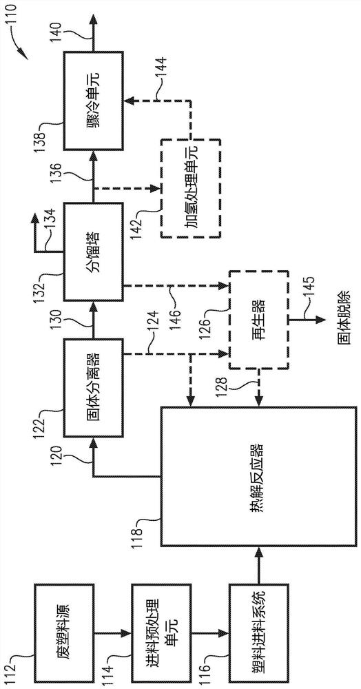
A predominantly C2 to C4 hydrocarbon cracker stream is combined with recycle content pyrolysis oil to form a combined cracker stream and the combined cracker stream is cracked in a cracker furnace to provide an olefin-containing effluent. The r-pyoil can be fed to a first coil while a second cracker feed with none of the r- pyoil or less of the r-pyoil is fed to a second coil, and both are cracked in a cracker furnace to form an olefin -containing effluent stream. Alternatively, the r-pyoil can be fed and distributed across multiple coils along with the non-recycle cracker feed. The furnace can be a gas fed furnace, or split cracker furnace. Further, a first cracker stream with r-pyoil in a first coil can have a lower total molar flow rate than a second cracker stream in a second coil in the same furnace.

Description

Background technique [0001] Waste materials, especially non-biodegradable waste materials, have a negative impact on the environment when disposed of in landfills after a single use. Therefore, from an environmental point of view, it is desirable to recycle as much waste as possible. However, recycling waste can be challenging from an economic standpoint. [0002] While some waste materials are relatively easy and inexpensive to recycle, others require extensive and expensive processing before they can be reused. Additionally, different types of waste often require different types of recycling processes. In many cases, expensive physical sorting of waste materials into relatively pure, single-component waste volumes is required. [0003] To maximize recycling efficiency, large-scale production facilities wish to be able to process feedstock with recycled content derived from a variety of waste materials. Commercial facilities involved in the production of non-biodegradable...

Claims


Application Information

Patent Timeline
IPC IPC(8): B01J19/00C10B53/02C10B53/07C10G1/02C10B55/00
CPCB01J6/008C10B53/02C10B53/07C10G1/02C10B55/00C10G2300/1011C10G2300/1003C10G2400/22C10G2300/1092C10G2300/1088C10G2300/4081C10G1/10C10G9/20C10G1/002C10L1/02Y02P30/20Y02E50/10C10G9/00C10G9/36C10G9/206C10G2400/20
Inventor 达里尔·贝汀肯尼·伦道夫·帕克迈克尔·加里·波拉塞克大卫·尤金·斯莱文斯基武显春小杰罗姆·伦纳德·斯塔维诺哈
Owner EASTMAN CHEM CO
Learn More