Pellet flue gas desulfurization, denitration and dust removal integrated treatment system and method

A technology for processing systems and flue gas, applied in gas treatment, chemical instruments and methods, sulfur compounds, etc., can solve the problems of energy and heat loss consumption, high processing costs, etc., to improve work efficiency, realize energy recovery and utilization, and realize recovery and the effect of repeated use

Pending Publication Date: 2022-01-18
CHINA CITY ENVIRONMENT PROTECTION ENGINEERING LIMITED COMPANY
View PDF1 Cites 0 Cited by
  • Summary
  • Abstract
  • Description
  • Claims
  • Application Information

AI Technical Summary

Problems solved by technology

However, this process needs to cool the high-temperature flue gas, and there are problems such as large energy and heat loss and high processing costs.

Method used


Image

  • Pellet flue gas desulfurization, denitration and dust removal integrated treatment system and method
  • Pellet flue gas desulfurization, denitration and dust removal integrated treatment system and method

Examples


Embodiment 1

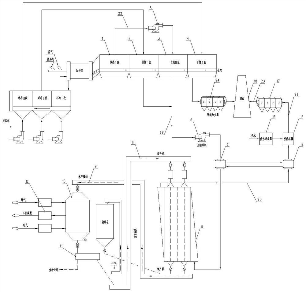
[0038] please join figure 1 , the present invention provides a pelletizing flue gas desulfurization, denitrification, and dust removal integrated treatment system, the system is used to process the flue gas generated by the pelletizing rotary kiln, the pelletizing rotary kiln is connected with the chain grate, and the chain The grate includes drying section 4, drying section 3, preheating section 2 and preheating section 1 connected in sequence; the integrated treatment system includes desulfurization subsystem, ammonia injection subsystem, denitrification and dust removal subsystem and heat exchange subsystem.

[0039] Among them, the desulfurization subsystem is connected to the flue gas outlet of the preheating section 2 and drying section 3 of the grate through the flue gas main pipe 19; the ammonia injection subsystem is connected to the outlet of the desulfurization subsystem through the first connecting pipe 20 It is used to spray ammonia on the flue gas after desulfur...

Embodiment 2

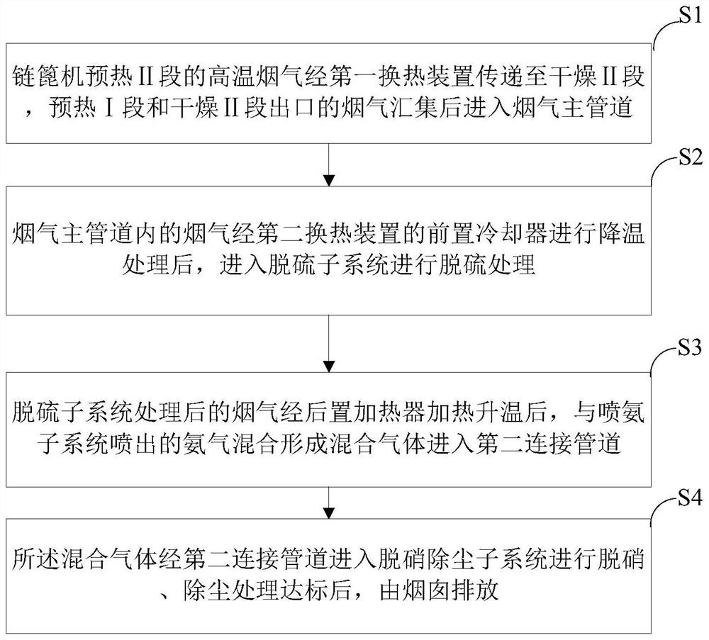
[0053] See figure 2 , the present invention also provides an integrated treatment method for pellet flue gas desulfurization, denitrification and dust removal, the method comprising the following steps:

[0054] S1. The high-temperature flue gas from the grate preheating section 1 is transferred to the drying section 3 through the first heat exchange device, and the flue gas from the outlet of the preheating section 2 and the drying section 3 is collected and then enters the main flue gas pipeline 19;

[0055] S2. After the flue gas in the flue gas main pipeline 19 is cooled by the pre-cooler 7 of the second heat exchange device, it enters the desulfurization subsystem for desulfurization treatment;

[0056] S3. After the flue gas processed by the desulfurization subsystem is heated by the rear heater 14, it is mixed with the ammonia gas emitted by the ammonia injection subsystem to form a mixed gas and enters the second connecting pipe 21;

[0057] S4. The mixed gas enters ...


PUM


Abstract

The invention provides a pellet flue gas desulfurization, denitration and dust removal integrated treatment system and method. The system comprises a desulfurization subsystem, an ammonia spraying subsystem, a denitration and dust removal subsystem and a heat exchange subsystem, wherein a first heat exchange device of the heat exchange subsystem is used for pumping high-temperature flue gas of a preheating section II to a drying section II to provide heat for drying green pellets; and a second heat exchange device of the heat exchange subsystem comprises a front cooler and a rear heater, so that proper treatment temperature can be provided for the desulfurization subsystem and the denitration and dust removal subsystem, and reutilization of heat energy and full recovery of energy can be realized. According to the integrated treatment system provided by the invention, the pellet flue gas is subjected to desulfurization, denitration and dust removal integrated treatment, meanwhile, energy and heat are recycled and reasonably utilized, the treated flue gas can meet the ultra-clean emission requirement, the investment and operation cost of the system is remarkably reduced, and the flue gas treatment efficiency is improved.

Description

technical field [0001] The invention belongs to the technical field of industrial waste gas treatment, and specifically relates to an integrated treatment system and treatment method for pellet flue gas desulfurization, denitrification and dust removal. Background technique [0002] The pellet plant has a large amount of smoke exhaust, and the main pollutant of the flue gas is NO X , SO 2 And dust, the pollutant concentration of emission is higher. In the ultra-clean emission requirements standard, the particulate matter limit of the flue gas emitted by the pellets is adjusted to 10mg / Nm 3 , Sulfur dioxide limit adjusted to 35mg / Nm 3 , Nitrogen oxide limit adjusted to 50mg / Nm 3 , which poses a higher challenge to pellet flue gas treatment technology. Therefore, the pellet flue gas must choose a process technology with high denitrification, desulfurization and dust removal efficiency and mature technology for flue gas desulfurization, denitrification, and dust removal. ...

Claims


Application Information

Patent Timeline
Patent Type & Authority Applications(China)
IPC IPC(8): B01D53/76B01D53/56B01D53/04B01D47/05B01D53/34B01D49/00B01D53/30C01B17/80
CPCB01D53/76B01D53/56B01D53/04B01D47/05B01D53/343B01D49/00B01D53/30C01B17/806B01D2258/0283B01D2253/102B01D2257/302Y02P70/10
Inventor 李军伟贾翠杰张兵吴继青徐超沈志鹏胡鑫罗海兵
Owner CHINA CITY ENVIRONMENT PROTECTION ENGINEERING LIMITED COMPANY
Why Eureka
Try Eureka