
System and method for preparing ammonia through urea hydrolysis based on peak regulation heat storage of coal-fired unit of thermal power plant

A coal-fired unit and urea hydrolysis technology, which is applied in the field of urea hydrolysis ammonia production system, can solve the problems of large volume of urea hydrolysis reactor, influence on power generation efficiency of unit, low utilization rate, etc., so as to improve flexibility and economy, reduce operation Cost, effect of improving safety

Pending Publication Date: 2022-02-18
XIAN THERMAL POWER RES INST CO LTD +1
View PDF0 Cites 0 Cited by
  • Summary
  • Abstract
  • Description
  • Claims
  • Application Information

AI Technical Summary

Problems solved by technology

The urea hydrolysis ammonia production technology has the advantages of high conversion rate, less by-products, and high safety. The conventional urea hydrolysis ammonia production technology extracts low-grade steam from the steam turbine as a heat source, and the steam is pumped and used immediately, which has a certain impact on the power generation efficiency of the unit. influences
In addition, the convective heat transfer coefficient of high-temperature steam is smaller than that of heat transfer oil. When steam is used as the heat source, the urea hydrolysis reactor has a large volume and is not convenient for layout.
At present, there are few technologies that efficiently combine the residual gas and electricity of coal-fired units during deep peak regulation with the ammonia production technology of selective catalytic reduction flue gas denitrification. The existing technologies are complex in design, cumbersome in operation, and low in utilization rate. advanced questions

Method used


Image

  • System and method for preparing ammonia through urea hydrolysis based on peak regulation heat storage of coal-fired unit of thermal power plant

Examples


Embodiment Construction

[0034] The present invention will be further described in detail below in conjunction with specific embodiments, which are explanations of the present invention rather than limitations.

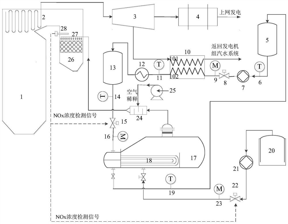
[0035] Urea hydrolysis ammonia production system based on peak regulation and heat storage of coal-fired units in thermal power plants, such as figure 1As shown, a gas unit consisting of a boiler 1, a steam turbine 3, and a generator 4, as well as a heat storage unit, a urea hydrolysis ammonia production unit, an SCR denitrification unit and a NOx concentration detection probe 28;

[0036] The heat storage unit includes a heat storage device 10, a heat transfer oil cold tank 5, a heat transfer oil hot tank 13, and an auxiliary electric heater 12; the heat storage device 10 is internally equipped with a heat storage medium, and through the heat storage medium is arranged Heat conduction heat storage circuit and heat release circuit; the heat storage circuit adopts the heat source pipeline 101 ...


PUM


Abstract

The invention discloses a system and method for preparing ammonia through urea hydrolysis based on peak regulation heat storage of a coal-fired unit of a thermal power plant. The system comprises the coal-fired unit, a heat storage unit and a urea hydrolysis ammonia production unit, wherein the coal-fired unit comprises a boiler, an SCR denitration unit arranged in the boiler, a steam turbine connected to an outlet of a steam coil of the boiler and a generator; an NOx concentration detection probe is arranged at an inlet of the SCR denitration unit; the heat storage unit comprises a heat storage medium, a heat storage loop and a heat release loop; the inlet end of the heat storage loop is connected with a steam outlet of the steam turbine, the outlet end of the heat storage loop is connected with a steam-water system of a generator set, the inlet end of the heat release loop is connected with an outlet of a heat-conducting oil cold tank, and the outlet end of the heat release loop is connected to an inlet of a heat-conducting oil hot tank. A heat source inlet of the urea hydrolysis ammonia production unit is connected with the outlet of the heat-conducting oil hot tank, a heat source outlet is connected with the inlet of the heat-conducting oil cold tank, and an ammonia gas outlet is connected with the SCR denitration unit; the signal output end of the NOx concentration detection probe is connected with the outlet of the heat conduction oil hot tank and a control valve of a urea solution inlet of the urea hydrolysis ammonia production unit.

Description

technical field [0001] The invention relates to the technical field of flue gas denitrification, in particular to a urea hydrolysis ammonia production system and method based on peak regulation and heat storage of coal-fired units in thermal power plants. Background technique [0002] With the rapid increase of installed capacity of my country's power grid, the mismatch between power supply and demand has become increasingly serious, and the phenomenon that residents' power consumption is far less than the power supply makes power plants' coal-fired units often operate in deep peak-shaving and low-load operation. In addition, with the continuous development of new energy power generation technology, the grid connection space of coal-fired units has been occupied on a large scale. In addition, new energy sources such as wind energy have anti-peaking characteristics such as large volatility and poor stability, which further brings huge challenges and restrictions to the peakin...

Claims


Application Information

Patent Timeline
IPC IPC(8): B01J7/02B01D53/86B01D53/56C01C1/08F28D20/00F28D20/02
CPCB01J7/02B01D53/8625C01C1/086F28D20/00F28D20/021B01D2251/2062Y02E60/14
Inventor 陆续韩伟张向宇付康丽吴庆龙张波刘雯
Owner XIAN THERMAL POWER RES INST CO LTD
Learn More